Siemens TXB1.P1-4 Instruções de instalação
Procurar online ou descarregar pdf Instruções de instalação para Unidade de controlo Siemens TXB1.P1-4. Siemens TXB1.P1-4 4 páginas. Tx-i/o bus interface module
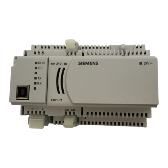
TX-I/O P1 Bus Interface Module
Product Description
The P1 Bus Interface Module (P1 BIM) enables
communication between a P1 Field Level Network
(FLN) and TX-I/O modules. It also provides 14.4 W
(0.6A at 24 Vdc) to power the TX-I/O modules and
external devices. External devices draw power from
the 24 Vdc and ground terminals on the TX-I/O
modules.
Figure 1. P1 Bus Interface Module Example (TXB1.P1-4).
Product Numbers
TXB1.P1
TX-I/O Bus Interface Module, P1
(10 modules, if needed may share
power with TXS1.12F4 TX-I/O
Power Supply)
TXB1.P1-4
TX-I/O Bus Interface Module, P1
(4 modules)
Warning/Caution Notation
WARNING:
Personal injury or property
damage may occur if you do not
follow a procedure as specified.
CAUTION:
Equipment damage or loss of
data may occur if you do not
follow a procedure as specified.
Item Number: 553-140, Rev. GA
Required Tools and Materials
•
Wire stripper/side cutter
•
Small flat blade screwdriver
•
Digital multimeter (DMM)
Expected Installation Time
7 minutes
Prerequisites
CAUTION:
No power wiring is connected to the field
panel controller or other TX-I/O
components at this time.
CAUTION:
The TX-I/O island bus must be mounted
on a DIN rail (1.38" × 0.3" × 0.04"
[35 mm × 7.5 mm × 1 mm]).
•
For energy management installations, NEMA
Type 1 or better enclosure with DIN rails and
source of 24 Vac.
•
For smoke control installations, PX Series
enclosures and service boxes. See the PX
Series Service Box Installation Instructions
(553-131).
•
If mounting in an enclosure:
−
Enclosure is installed.
−
The power source is installed, as
applicable.
−
The power is OFF.
•
All necessary wiring is pulled and terminated
per the layout drawing.
•
Power and communication wiring is terminated
to the removable plugs supplied with the
devices.
Installation Instructions
Document No. 553-140
November 4, 2019
Page 1 of 4