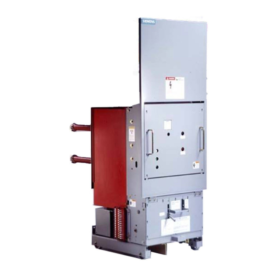
Siemens 15-FSV-750 Instalação, operação e manutenção - Página 37
Procurar online ou descarregar pdf Instalação, operação e manutenção para Interruptor Siemens 15-FSV-750. Siemens 15-FSV-750 48 páginas. Vacuum circuit breakers fsv series and msv series

Vehicle
Description
Vehicle Function and Operational
Interlocks
Type MSV and FSV vacu u m circuit breakers are comp rised
mainly of the interru pter/operator su b-assembly fitted to a ve
hicle. This interru pter/operator su b-assembly is an integ ral ar
rangement of operating mechanism, d ielectric system . vacuum
interrupters, and means of connecting the p ri mary c i rcuit. The
vehicle supports the interru pter/operator su b-assembly, pro
viding mobility and fully coordinated appl ication in Siemens
" 0 "
type
and "F" switchgear.
Successful coordinated application of the fully assembled MSV
or FSV vacuum breaker is achieved thru precise fixtured align
ment, and important functional interlocking .
Alignment
E lements of the vehicle structu re, which are assemb l ed under
fixture control and then are secu red and p inned i n place. in
clude the following (no adju stments are requ i red):
Side c hannels which p rovide su pport to the interru pter/op
•
erator sub-assembly are fixtu red square (90) to the wheel
axle holes in the vehicles base.
The primary c i rcuit conductors are fixtu red to appropriate el
•
evation, phase spacing and al ignment to the inside surface
of the guide bar. The g u i d e bar, i s set i n the fixture firmly
secu red and ten pinned i n place.
Secondary d isconnects are fixtu red and pinned in place
•
Shutter cam which raises and lowers protective pri mary
•
bushing barriers, is fixtu red firmly secu red and pinned.
· Breaker g rounding contacts, are al igned and securely bolted
in place.
Closing spring d ischarge roller, i s located and sec u red .
•
The hi nged protective barrier is aligned , adju sted vertically
•
and then pinned in place.
Thus, all those features which must align with elements of the
switchgear "d raw out" enclos u re , are precisely set, firmly se
cured and pi nned whi l e the complete b reaker is located i n a
rigid fixture.
Interlocks
A
I noperative or by-passed interlocks will cause
death. serious personal inJury and property
damage
M e c h a n i c a l and e l e c t r i c a l i n t e r l o c ks are
provided as integral com ponents of this
equi pment to ensure safe use. Interlocks must
be i n operation at all times. Read this in
s t r u c t i o n m a n u a l . Know a n d u n d erstand
correct i nterlock fu nctio n . Check i nterlock
f u n c t i o n p r i o r to i n s e rt i n g b re a k e r i n to
switchgear cub1cle.
Breaker Racking Interlock
(Lever Type)
Reference: Figu res 24a & 24b
The racking interlock functions to block movement of the cir
cuit breaker from the connected or test positions whenever the
breaker is closed , and to maintain the breakers mechanism in
a "trip free" state whenever the c i rcuit breaker is " released"
The breaker i s
closed
whenever the primary c i rc u it is com
•
pleted through the vac u u m interrupter contacts. This closed
condition i s caused by rotation of the breaker shaft, 63 to the
position shown in figure 24b.
The breaker is released (free to rack) when the plunger shown
•
in figure 24a is elevated sufficiently to c lear the slot in the
c u bicle rai l .
Fu nction o f t h e c losed b reaker racking release is in itiated by
elevating the racking release handle. This action causes the
interlock bell crank, 1 , to attempt CCW rotation. If the breaker
were closed, the bell crank will rotate incrementally causing
the "push rod ", 2 , to rise thru the action of crank, 1 , and link. 3 .
This action w i l l b e i mmediately blocked, because the p u s h rods
"mushroom" head will encounter a cam s u rface of l ever 64 . 3
o n the b reaker shaft, 63, typically after 1 to 2 m m ( 040 to . 080
inches) of motion. With motion blocked after this short move
ment, it is not possible to raise the p l u nger above the cubicle
rai l . Thus, The Breaker Can Not Be Released For Racking
When The Primary Contacts Are Closed.
If the breakers primary contacts were open , the cam s u rface
of lever 64 . 3 on the breaker shaft, 63 will have rotated beyond
the push rods " m u shroo m " head al lowing the push rod to nse
freely
Page 32
DANGER
