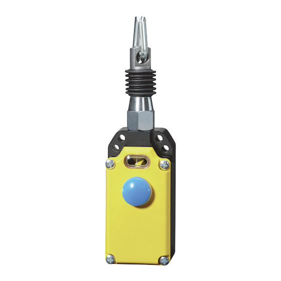
Siemens SIRIUS 3SE7140 Series Manual de Instruções - Página 2
Procurar online ou descarregar pdf Manual de Instruções para Interruptor Siemens SIRIUS 3SE7140 Series. Siemens SIRIUS 3SE7140 Series 10 páginas. Cable-operated switch with / without latching
Também para Siemens SIRIUS 3SE7140 Series: Manual de Instruções (9 páginas), Manual de Instruções (7 páginas), Instruções de funcionamento originais (8 páginas)

SIRIUS
Position Switches with Separate Actuator
Operating Instructions
Read and understand these instructions before installing, operating, or
maintaining the equipment.
DANGER
!
Hazardous voltage.
Will cause death or serious injury.
Disconnect power before working on equipment.
Reliable functioning of the equipment is only ensured with certified
components.
Important notice
The products described herein are designed to be components of a
customized machinery safety-oriented control system. A complete
safety-oriented system may include safety sensors, evaluators, actua-
tors and signaling components. It is the responsibility of each company
to conduct its own evaluation of the effectiveness of the safety system
by trained individuals. Siemens AG, its subsidiaries and affiliates (col-
lectively "Siemens") are not in a position to evaluate all of the charac-
teristics of a given machine or product not designed by Siemens.
Siemens accepts no liability for any recommendation that may be
implied or stated herein. The warranty contained in the contract of sale
by Siemens is the sole warranty of Siemens. Any statements contained
herein do not create new warranties or modify existing ones.
Design / Operating principle
When the wire cable is pre-stressed, the contacts 21-22 are closed and
the contacts 13-14 are open. When the wire cable is being pulled or if it
breaks, the contacts 21-22 are opened and the contacts 13-14 are
closed. In the case of cable-operated switches with latching, the con-
tacts 21-22 are latched open and the contacts 13-14 are latched closed
when the wire cable is being pulled or if it breaks. The contacts can be
unlatched by either pushing the pushbutton or using the key.
It is only possible to unlatch the contacts in the middle position
(pre-stressed position.
Installation
When installing, the switch must be pre-stressed until the switch cam is
in the middle position.
The cable-operated switch must be installed so that safe manual
unlatching is possible.
Before installing the sheathed cable, the sheath must be removed from
the wire cable in the vicinity of the clamps. The wire cable must be
installed according to the installtion instructions.
As the grommet thimble deforms when the wire cable is being pulled,
the wire cable should be vigorously pulled several times after
installation. The tension of the wire cable must be subsequently
regulated by means of either a cable clamp or via the eyebolt or tension
jack.
Due to the tendency of the wire cable to expand when exposed to heat,
the ambient temperature range decreases with increasis cable length.
2
Order No.: 3ZX1012-0SE70-2AA1
Note
The switch may only be operated by pulling the sheathed cable and
never by removing the mechanism or the drawgear using tools.
The operator must convince himself/herself regularly of the safe func-
tioning of the EMRGENCY STOP device.
Technical data
Standards applied
Enclosure
Cover
Degree of protection
Switching system
Connection type
Cable entry
Cable length
Spring resistances
Mech. service life
Permiss. operating temperature –25°C up to +70°C
Permiss. electr. load
Short-circuit strength
Indicator lamp
Degree of protection
Permiss. electr. load
Installation notes (see Fig. 3A and 3B)
A
Recommended cable lengths S (m) for safety cable-operated switches
dependent upon ambient temperature range T (°C).
B
Attention: Cable supports spaced as follows are required:
3SE7150- all 3 m
3SE7140- all 5 m
3SE7120- all 2,5 m
3SE7120-
3SE7140-
3SE7150-
English
IEC 947-5-5/EN 60947-5-5
GD-AL alloy, painted
Impact-resistant thermoplast
IP65 acc. to IEC 529 / EN 60 529
A acc. to IEC 947-5-5
1 NC contact and 1 NO contact, snap
contact
Positively-driven NC contacts
M3.5 scew-type connection;
self-lifting U-bolt
3SE7 140-...00 = 1 x M16x1,5
3SE7 150-...00 = 2 x M20x1,5
3SE7 140-...0 AS = 2 x M25x1,5
3SE7 120-... = 2 x M20x1,5
3SE7 140-... max. 50 m
3SE7 150-... max. 25 m
3SE7 120-... max. 10 m
(observe ambient temperature)
3SE7150- 200N
3SE7120- 55N
6
> 10
switching cycles
(observe cable length)
400 V AC / 6 A (AC-15)
6 A (time-lag)
Indicator lamp not connectedn
IP65
24 V =, < 45 mA, red
