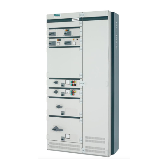
Siemens SIVACON S 8PQ9800-3AA48 Manual de Instruções - Página 21
Procurar online ou descarregar pdf Manual de Instruções para Interruptor Siemens SIVACON S 8PQ9800-3AA48. Siemens SIVACON S 8PQ9800-3AA48 40 páginas. Design-verified low-voltage switchboard

- 1. Table of Contents
- 2. Sivacon Bauartgeprüfte Niederspannungsschaltanlage S8 - Felder mit Abzweigen in Einschubtechnik Design-Verified Low-Voltage Switchboard S8- Cubicles with Feeders in Withdrawable Design Betriebsanleitung / Operating Instructions Bestell-Nr. / Order No.: 8P
- 3. Description of the MCC Cubicle
- 4. Electrical Connections
2.2.1.2 Anschlussquerschnitte
Abzweighöhe 100mm/ feeder height 100mm
Abzweig-
Klemmenbezeichnung/
nennstrom
Terminal
designation
35A
8WA1..4
eindrähtig/ solid
1)
flexibel/flexible
2)
Feindrähtig mit Aderendhülse/Finely stranded with end sleeve
3)
Fach
250A (>100mm)
Compartment up to 125A
(>100mm)
Fach >250A 630A
Compartment >250A 630A
Fach >250A 630A
Compartment >250A 630A
Vertikale PE-Schiene im
Kabelanschlussraum für
Abzweige 63A
Vertical PE-bar in cable
connection compartment for
feeders 63A
Vertikale PE-Schiene im
Kabelanschlussraum für
Abzweige > 63A
Vertical PE-bar in cable
connection compartment for
feeders > 63A
Vertikale N(PEN)-Schiene im
Kabelanschlussraum
Vertical N(PEN)-bar in cable
connection compartment
*Für Kabel mit kleinen Querschnitten können auch geeignete Klemmen verwendet werden.
*For cables with small cross sections, suitable terminals can be used.
2.2.2 Steuerstromkreise
Steuerleitungen an Kabeltrageisen befestigen. Die Leitungen zum
Querverdrahtungsraum sind durch die vorgesehenen Ausbrüche zu
führen, bei Anschluss in der Anlage von hinten durch den oben
liegenden Kabelkanal nach vorne in den Querverdrahtungsraum. Die
Steuerleitungen werden gemäß Schaltplan an die Reihenklemmen
des Klemmenadapters angeschlossen.
2.2.2.1 Steuerklemmblock mit Push-In-Anschluss
Der Steuerklemmblock weist je PIN zwei Klemmstellen auf. Das
Kabel mit aufgepresster Aderendhülse kann direkt in die Klemme bis
zum Anschlag eingeschoben werden und wird dann sicher geklemmt.
Zum Lösen des Kabels aus der Klemme ist mit einem geeigneten
Schraubendreher (z.B. Fabrikat von Phoenix Contact Artikelbezeich-
nung SZF 0-0,4x2,5, Bestell-Nr 1204504) die Klemme durch Ein-
schieben neben der Klemmstelle zu öffnen.
8PQ9800-3AA48
Klemmen-
Querschnitt
größe
Crosssection
Terminal
[mm²]
size [mm²]
1,5 – 16
16
2,5 – 25
1,0 – 16
Anschlusspunkte
Größe der Ver-
Connection points
schraubung
Size of screwed
joints
1
M10
1
M12
2
M12
-
M12
M12
2.2.1.2 Cable cross-sections
Anziehdrehmoment
= Prüfdrehmoment
Tightening torque
= Checking torque [Nm]
(1
1,2
(2
(3
Max. zulässige Kabelquerschnitt bzw.
Kabelschuh (DIN 46235) [mm
2
Max. permitted cable cross-section or
cable lug* (DIN 46235) [mm
]
2
1x185 oder 2x120
1x240 oder 2x120
2x240 oder 4x120
16 mm
2
Anschluss mit Universal-Leiter-
Anschlussklemmen
Connection with universal-conductor-
terminals
240
240
2.2.2 Control circuit
Fasten control lines to cable brackets. The cables to the transverse
wiring compartment must be fed through the cutouts provided. For
rear cable connection the cable channel above the functional space
must be used to get the cables to the transverse wiring compartment
in the front.
The control cables are connected to the modular terminals of the
terminal adapter acc. to the circuit diagram.
2.2.2.1 Control-terminal block with push-in terminal
The control terminal block has two clamp points per pin. A cable with
a clamed-on end sleeve can be inserted directly into the terminal up
to the end stop.
To disconnect the cable from the terminal, the terminal should be
opened by inserting a suitable screwdriver (e.g. from Phoenix Con-
tact with product code SZF 0-0,4x2,5, order no.: 1204504) next to the
clamp point.
Schraubwerkzeug
Bolting Tool
Schraubendreherschneide
0,8 x 4 mm
Screwdriver blade 0.8 x 4 mm
Anziehdrehmoment [Nm]
]
Tightening torque [Nm]
40
70
70
4
70
70
19
