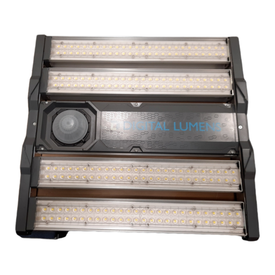
Digital Lumens DLE-18-HV Manual de instruções de instalação - Página 3
Procurar online ou descarregar pdf Manual de instruções de instalação para Equipamento de iluminação Digital Lumens DLE-18-HV. Digital Lumens DLE-18-HV 16 páginas.

Instructions
Product Safety
This product must be installed in accordance with the applicable
!
installation code by a person familiar with the construction and
operation of the product and the hazards involved.
To avoid risk of electrical shock, disconnect power before installing,
wiring, or servicing fixture.
Fixture has no user-serviceable parts. Do not open fixture
compartments, except as noted in this document.
Do not apply paint, lubricants or other coatings to fixture, suspension
!
cables, or fasteners.
If you attach a safety cable, attach it to the fixture in accordance with all
!
national, state, and local construction codes.
See illustrations on pages 1-2.
1. Verify Optic Type
Use the optic type specified in the project plan: Narrow, Wide, Aisle,
or Diffuse. The optic type (excluding diffuse) is imprinted on the
optical plastic.
If installing a sensor mask, refer to
2. Add Barcode Labels to Sticker Book
Detach the plastic bag from fixture, then remove barcode label from bag
and affix to sticker book depicting the intended installation location of
the fixture.
3. Adjust the Light Bars
Manually rotate each light bar, with LEDs facing outward until it clicks
into desired position, depressing the light bar endplate button
if present.
Refer to
Appendix B: Lightbar Setting
4. Install the Fixture
a. Refer to the sticker book to confirm correct location and aisle
direction of the fixture.
b. Secure cable to a beam or truss.
c. Secure cable to fixture short edge (preferred method).
d. Note 60° maximum cable angle.
e. If connecting to a DLE-12/18/24 fixture long edge, attach one
DHHSO (DLE, Hanging Hardware, Standoff) per tab on side with
power input.
5. Make Electrical Connection
To avoid risk of electrical shock, disconnect power before installing,
wiring, or servicing fixtures.
Do not rest extra power cable on the cooling fins.
Option 1: Cable and Plug Standard Wiring Procedure
a. In accordance with national, state, and local electrical code, connect
the power cable to the line circuit.
b. Plug the modular connector end of the supplied power cable into
the matched receptacle on the fixture.
c. Ensure that the hood on the modular connector is seated.
Read these instructions before using product.
!
Appendix A
for instructions.
Options.
Do not use fixture if the housing, suspension cables, optics, or power
!
cable are damaged.
Do not touch the optics modules with your fingers, as you may damage
!
the optical coating. In the event you need to clean an optics module,
use a damp cloth and gently swab the affected area.
Only handle fixture by the end caps. Do not grasp or handle fixture
!
using the light bars.
For use in environments where an accumulation of non-conductive dust
!
on the luminaire may be expected.
Option 2: Internal Wiring Procedure
Only use flexible conduit — rigid conduit is not compatible.
Do not rest extra conduit on the cooling fins.
a. With a T15 Torx driver, remove the captive Torx screws (6x for DLE
12/18/24; 12x for DLE 48) holding the compartment cover and
remove the cover.
b. Turn over the fixture. Drill an opening in the top of the fixture
suitable for a 1/2-inch trade size conduit connector. Use the circular
depression on top of the fixture as a guide.
c. Fit 1/2-inch flexible conduit through the opening.
d. Inside the wiring compartment, use a small screwdriver to release
the three conductors connected to the back of the modular
connector.
e. Pull power cable through the conduit into the compartment.
f. Attach DLE direct wiring plug (sold separately).
g. In accordance with national, state, and local electrical code, connect
the three conductors inside the fixture to the incoming conductors.
h. Replace the compartment cover and retaining screws.
6. Level the Fixture
Use a box level or similar to level the fixture by adjusting the aircraft
cable length.
7. Verify the Sticker Book
To prevent issues during fixture programming, ensure that the placement
of the barcode label in the sticker book corresponds to the fixture's
physical location in the facility.
Product Ratings
!
DLE-12-ST: 120-277 VAC, 50/60 Hz, 113 W max, 0.94 A max
DLE-18-ST: 120-277 VAC, 50/60 Hz, 168 W max, 1.40 A max
DLE-24-ST: 120-277 VAC, 50/60 Hz, 228 W max, 1.90 A max
DLE-48-ST: 120-277 VAC, 50/60 Hz, 456 W max, 3.80 A max
DLE-12-HV: 347-480 VAC, 50/60 Hz, 122 W max, 0.35 A max
DLE-18-HV: 347-480 VAC, 50/60 Hz, 174 W max, 0.50 A max
DLE-24-HV: 347-480 VAC, 50/60 Hz, 226 W max, 0.65 A max
DLE-48-HV: 347-480 VAC, 50/60 Hz, 455 W max, 1.31 A max
ENGLISH
3
