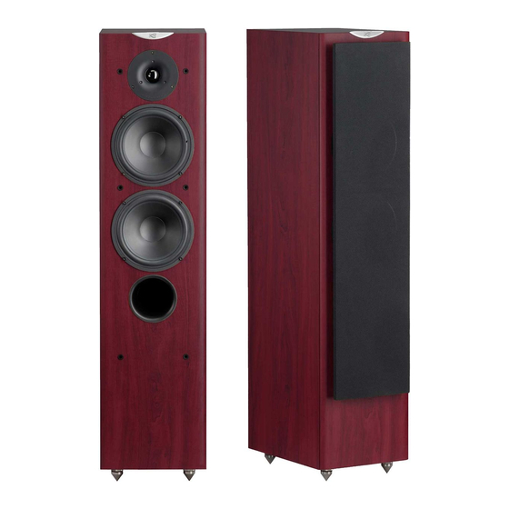
CABASSE Jersey MT360R Manual do Proprietário - Página 9
Procurar online ou descarregar pdf Manual do Proprietário para Altifalantes CABASSE Jersey MT360R. CABASSE Jersey MT360R 17 páginas.

e n g l i s h
speakers are below it, and below the screen if the main spea-
kers are above. The centre speaker should also, if possible, be
set slightly back from the others, so that it is located at the same
distance from the listener as the main speakers.
The rear speakers or surround should be placed against the
side walls, at listening height. They should not be positioned
far behind the listening zone.
The subwoofer should be placed in the front listening area,
its position against a wall reinforces the extreme low register and
limits the reflections between 80 and 200 Hz. However to
obtain the best result, it is always necessary to carry out tests
according to the acoustics of the room.
Your AV processor enables the adjustment in level and delay of
each of the 5/6/7 channels of your system. Fine-tuning is neces-
sary to obtain a perfect sound stage.
Turn off all the amplifiers before interconnecting them to the
loudspeakers. In order to connect loudspeakers properly, it is
most important to keep in mind the following two factors:
cable section and phase.
CONNECTION
Cable section
To get the full sonic
Lenght between
amplifier and loudspeakers
potential of Cabasse
loudspeakers and
avoid power losses,
the cables connecting
the speakers to the
power amplifier must have the lowest possible electrical resis-
tance. To help you in choosing the correct cable gauge, follow
diagram.
Phase
In order to maintain the phase relationship and frequency
balance of the loudspeaker system, both loudspeakers must be
properly connected to the power amplifier. When properly
connected, the cones of the drivers of both loudspeakers will
move in the same direction when driven by identical speakers
will move in the same signals. If the cones move in opposite
directions, the resulting out of phase signals will create a per-
ceptible power loss, particularly in the low frequencies. The
stereophonic message will also be degraded. Amplifier and
speaker manufacturers typically indicate connection polarity in
one of two ways: red and black or plus and minus. In either
case, always connect red or plus to red or plus and black or
minus to black or minus. Connections should be identical for
both channels. To check that the speakers are in correct pha-
se, switch the system to mono while music is being played. if
the amplifier does not have a phase inversion switch, it will
be necessary to change over the connections on one only of the
loudspeakers. If in correct phase, the image should be dis-
tinctly located between the loudspeakers with a slight loss of
recommanded
section
4.5 m
1.5 mm
2
6 m
2 mm
2
7.5 m
2.5 mm
2
9 m
3 mm
2
12 m
4 mm
2
bass and low midrange level. If the image is confused and not
centrally located and there is a drastic loss of bass and low
midrange level, recheck your connections.
HOME THEATER CONNECTIONS WITH
AN ACTIVE SUBWOOFER
Subwoofer positioning
With a crossover point below or around 150 Hz, the installa-
tion position of subwoofers is not limited as human ears and
brains are not able to identify the emitting point of such low
frequencies. To get the best result, it is recommended to try dif-
ferent positions and choose the one giving the best response
in the low frequencies, taking into account the room acoustics.
Hooking up the subwoofer
2 possibilities are offered to connect the subwoofer with your
system:
the low level one requiring the use of the Cinch RCA LINE IN
9
and LINE OUT
terminals and shielded coaxial connectors,
the high level one requiring the use of the FROM RECEI-
0
-
VER
and TO SPEAKERS
speaker cables.
The inputs are stereo ones, the mix of the L (left) and R (right)
low frequencies being done by the amplifier of the subwoofer.
If the input signal is already mono, only one input L (left) or R
(right) should be used.
Interconnections with the Cinch RCA LINE IN
9
and LINE OUT
connectors
Connections to the LINE IN
If your preamplifier or your integrated amplifier is fitted with
a stereo low-level output, then connect its L (left) and R (right)
outputs to the L (left) and R (right) LINE IN
woofer. If your amplifier offers a one mono output, connect it
to either the L (left) or the R (right) subwoofer LINE IN
Connections from the LINE OUT
The signal from the L (left) and R (right) LINE OUT
tors is the one being brought in by the L (left) and R (right) LINE
8
IN
connectors filtered at 40 Hz. These outputs can thus
be used to bring the signal to the amplifier powering the main
loudspeaker.
Attention,
before operating the unit,
be sure that the
operating voltage
of your unit is identical
with that of your local
power voltage.
8
terminals and standard loud-
8
8
0
inputs of the sub-
0
inputs.
9
9
connec-
