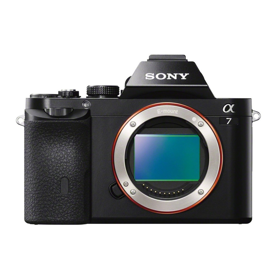
Sony Alpha ILCE-7R Manual de serviço - Página 14
Procurar online ou descarregar pdf Manual de serviço para Câmara digital Sony Alpha ILCE-7R. Sony Alpha ILCE-7R 25 páginas. Interchangeable lens digital camera

2-1-6. IMAGER BLOCK SECTION
ns: not supplied
258
254
Mount Section
(Note 2, 3)
(See page 2-10)
254
(Note 2, 3)
#197
254
(Note 2, 3)
Ref. No.
Part No.
Description
251
1-886-243-11
ISP-008 FLEXIBLE BOARD
252
1-886-244-11
ISL-008 FLEXIBLE BOARD
253
A-1976-127-A
MECHA DEVICE SERVICE (3000) (ILCE-7R)
(including IC6101 (CMOS imager) and IS-111 complete
board) (Note 4)
253
A-1976-128-A
MECHA DEVICE SERVICE (3100) (ILCE-7/7K)
(including IC6101 (CMOS imager) and IS-111 complete
board) (Note 4)
* 254
Selection Parts IM WASHER (C), ADJUST (Note 2, 3)
ILCE-7/7K/7R_L2
257
253
(including IC6101 (CMOS imager)
and IS-111 complete board)
(Note 4)
3
256
4
255
#238
1
ns
#267
(Note 1)
2
Imager Unit Section
(See page 2-9)
ns
Ref. No.
Part No.
Description
255
A-1902-075-C
MB CHARGE UNIT (456)
256
1-490-193-21
SHUTTER UNIT (AFE-3313)
257
4-480-795-01
BUTTON, LENS LOCK (779)
258
4-489-471-01
SHEET DP, N FRAME (779)
#197
4-185-990-01
MB SCREW, CHARGE UNIT FIXED
#238
4-287-436-01
SCREW (M1.7)
#267
4-287-436-21
SCREW (M1.7) (Note 1)
DISASSEMBLY
1. Remove in numerical order (
#267 X 3
2
Back View
Screw
#197: M1.6 X 4.5 (Tapping)
#238:
(Silver)
4-185-990-01
1.6
4.5
252
251
Note
Note 1: Refer to "Assembly-1: Screw tightening sequence when
assembling the IM plate (3000)".
Note 2: The IM adjust washers (C) differ in thickness.
Make sure to return the removed IM adjust washers to origi-
nal places.
When replacing IM adjust washers, refer to "SELECTION
#267
PARTS" If the original state cannot be restored due to loss
(Note 1)
of the IM adjust washer, for example, replace the Mecha
Device Service (3000/3100).
Note 3: Refer to "Assembly-2: IM Adjust Washer (C) putting posi-
tion" when you assemble.
Note 4: Precautions for Replacement of the Front Block Assy Ser-
vice
As Front Block Assy Service may be damaged by static
electricity from its structure, handle it carefully like for the
MOS IC.
In addition, ensure that the receiver is not covered with
dusts nor exposed to strong light.
SELECTION PARTS
Ref. No.254
Select the optimum thickness of washer.
Part No.
Description
* 4-185-999-01
IM WASHER (C), ADJUST (t = 0.05)
* 4-185-999-11
IM WASHER (C), ADJUST (t = 0.1)
* 4-185-999-21
IM WASHER (C), ADJUST (t = 0.15)
* 4-185-999-31
IM WASHER (C), ADJUST (t = 0.2)
* 4-185-999-41
IM WASHER (C), ADJUST (t = 0.25)
2-8
) in the left figure.
1
to
4
#238 X 3
4
Back View
#267
M1.7 X 3.5
#267: M1.7 X 5.0
(Black)
(Red)
4-287-436-01
4-287-436-21
1.7
1.7
3.5
5.0
Note 1: "Assembly-1: Screw tightening sequence when assembling
the IM plate (3000)" を参照してください。
Note 2: IM調整ワッシャ (C) は,それぞれ厚さが異なります。取り外
したIM調整ワッシャは,必ず元の位置に戻してください。
ま た,IM調 整 ワッシャを 交 換 す る 際 は, "SELECTION
PARTS"を参照してください。IM adjust washerを紛失するな
どして元の状態に戻せなくなった場合は,Mecha Device
Service (3000/3100) を交換してください。
Note 3: 組立時は "Assembly-2: IM Adjust Washer (C) putting posi-
tion" を参照してください。
Note 4: フロントブロックAssy サービス交換時の注意
フロントブロックAssy サービスは構造上,静電気により破壊
される恐れがあるため,MOS ICと同様に注意して取り扱って
ください。
また,受光部にはゴミの付着,および強い光がはいることの
ないように注意してください。
Part No.
Description
* 4-185-999-51
IM WASHER (C), ADJUST (t = 0.3)
* 4-185-999-61
IM WASHER (C), ADJUST (t = 0.35)
* 4-185-999-71
IM WASHER (C), ADJUST (t = 0.4)
* 4-185-999-81
IM WASHER (C), ADJUST (t = 0.45)
* 4-185-999-91
IM WASHER (C), ADJUST (t = 0.495)
#238
