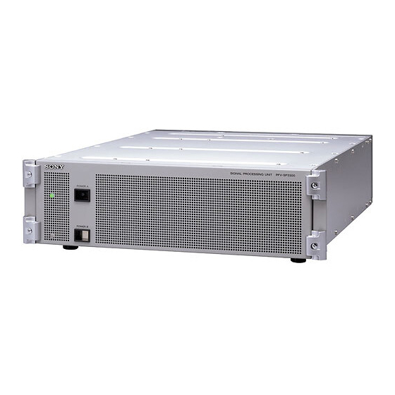
Sony PFV-SP3300 Manual de manutenção - Página 13
Procurar online ou descarregar pdf Manual de manutenção para Sistema estéreo Sony PFV-SP3300. Sony PFV-SP3300 40 páginas. Signal processing unit, backup power supply unit
Também para Sony PFV-SP3300: Manual de instalação (16 páginas), Manual de operação (18 páginas), Manual de instruções (18 páginas)

1-7. Replacement of IC Link
w
An IC link is critical parts to safe operation.
Replace this component with Sony parts whose part
numbers appear in this manual published by Sony.
If not, this may cause a fire or electric shock.
Be sure to use the specified component in this manual.
The IC link is mounted on the CN-2122 and IF-828 boards.
Be sure to replace with the specified IC link as shown
below after removing the foreign substances that may
cause the shorts.
CN-2122 board
Ref No. (Address) Description
PS1(B-1)
Circuit Protector
IC link 2A
IF-828 board
Ref No. (Address) Description
PS501(B-2)
Circuit Protector
IC link 2A
1-8. Extension Board
The following extension boards are ready for PFV-SP3300
as optional accessories.
Extension board
Parts No.
EX-833
A-8327-356-A
EX-834
A-8327-357-A
This section describes how to install and remove the EX-
833 and EX-834 boards in and from the PFV-SP3300.
Installation (Main board)
1. Turn off the power switches of PFV-SP3300.
2. Remove the front panel. (Refer to Section 1-1.)
3. Remove the board retainer. (Refer to Section 1-6-1.)
4. Remove the board to be extended. (Refer to Section 1-6-1.)
5. Insert the EX-833 board along the board guides.
6. Insert the EX-833 board into the slot as far as it will go
and securely connect it to the connector on the MB-
915 board.
7. Insert the board to be extended along the guides on the
EX-833 board.
PFV-SP3300
Parts No.
!1-533-282-21
Parts No.
!1-533-282-21
Apply to
For main board
For connector panel
8. Push the board to be extended and securely connect it
to the EX-833 board.
Board guides
Guide
Extension board
(EX-833)
Guide
Guide
Guide
Board to be extended
(Main board)
Removal
1. Pull out the extended board from the EX-833 board.
2. Pull out the EX-833 board from the slot.
3. Reinstall the extended board in the slot.
1-7. Replacement of IC Link
1-8. Extension Board
MB-915 board
Extension board
(EX-833)
1-7 (E)
