Digitrax PM42 Manual - Página 10
Procurar online ou descarregar pdf Manual para Unidade de controlo Digitrax PM42. Digitrax PM42 16 páginas.

5.0 PM42 Option Switch (OpSw) Set Up
The PM42 OpSw settings are used to set up the PM42 for setting up the trip
current, short circuit management (including sensitivity), and/or auto-reversing.
Follow the steps outlined below to set up OpSws according to the TABLES
below.
Connect a DT series throttle (with battery installed) to the LocoNet connector
on your powered PM42 to read back and make changes to the PM42's option
switches (OpSws).
The factory default setting on all PM42 OpSws is "thrown" or "t". This setting
will operate each section of the PM42 as a short circuit manager.
To Change PM42 OpSw settings:
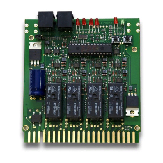
1. Enter option switch mode by pressing the "OPTION" button on the
PM42 for about 1 second and then releasing it. The green "ID" LED
and red "OPTION" LED will flash alternately to indicate that you
have entered option switch mode.
2. Connect any Digitrax DT series throttle to the PM42's LocoNet con-
nector. Note that because the throttle's switch control mode is used
to change the PM42's OpSw settings, each time you change the
PM42's option switch settings you will also send switch commands
to the layout any time you are connected to LocoNet and the layout.
3. If the PM42 is connected to a working LocoNet (via a 6 conductor
LocoNet cable), skip to step 4 since the LocoNet termination jumper
is not needed. If the PM42 is not connected to a working LocoNet,
move the LocoNet termination jumper so that it is across both pins.
The LocoNet termination jumper is, located behind the RJ12 sockets
on the PM42 board.
4. Follow the instructions for the throttle you are using to enter switch
control mode on the throttle. Select the switch address that corre-
sponds to the OpSw number you want to change. Press the "c" or "t"
button to change the OpSw setting as desired.
5. When OpSw set up is complete, press the PM42's "OPTION" button
and the unit will exit option switch mode. If you moved the LocoNet
termination jumper in step 3 above, return it to its original position
(leave it attached to one pin so that you don't lose the jumper).
9
