Cisco SCE8000 GBE Manual de início rápido - Página 5
Procurar online ou descarregar pdf Manual de início rápido para Hardware de rede Cisco SCE8000 GBE. Cisco SCE8000 GBE 25 páginas. 10gbe platform
Também para Cisco SCE8000 GBE: Manual de configuração (18 páginas), Procedimentos de remoção e substituição (36 páginas), Instalação (21 páginas)

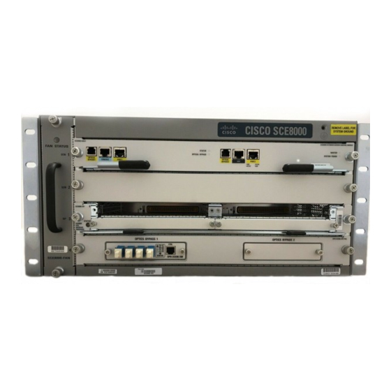
Figure 2
Installing the Cisco SCE8000 Chassis in the Rack
FA N ST
SCE 8000
AT US
-SCM -E
SC M
1
OPT ICAL
BYP ASS
CON SOL
E
POR T 1
10 100
LINK
1000
ACTI VE
SCE 8000
-SCM -E
SC M
2
OPT ICAL
BYP ASS
CON SOL
E
POR T 1
10 100
LINK
1000
ACTI VE
SCE 8000
-SIP
3
SIP
4
TX
SC E8 00
TX
0- FA N
RX
RX
Step 4
Install the eight (four per side) 12-24 x 3/4-inch or 10-32 x 3/4-inch screws through the holes in the bracket and into
the threaded holes in the equipment rack posts.
Use a tape measure and level to verify that the chassis is installed straight and level.
Step 5
Installing an Optical Bypass Module
Two installation options exist for external bypass modules:
• Chassis mount panel—This panel is mounted on slot #4 of the SCE 8000 chassis. It hosts two optical bypass modules, which
will serve the two traffic links supported by one Cisco SCE 8000 chassis.
• External mounting panel—This panel can be mounted in any 19-inch rack. It hosts up to 4 optical bypass modules, which
serve four traffic links supported by two Cisco SCE 8000 platforms.
For external mounting, install the external mounting panel in the 19-inch rack. Screw the mounting panel to the rack
Step 1
using four 3/4-inch screws, two on each side, through the holes in the mounting panel and into the threaded holes in
the rack posts. For internal mounting, the SCE8000 chassis is shipped with the chassis mounting panel installed in
slot 4.
Remove the module filler plate covering the subslot in the mounting panel by loosening the two screws.
Step 2
Step 3
Carefully insert the optical bypass module into the subslot (no guide rails exist) and tighten the captive screws on either
side of the module (Figure 3).
STA TUS
OPT ICA
L BYP ASS
STA TUS
OPT ICA
L BYP ASS
SPA -1X1
0GE -L-V2
SPA -1X1
0GE -L-V2
TX
A C
TX
CT RL
B
D
A B
RX
C
RX
D
STA TU
OP TIC AL
S
BY PA SS
OP B-S
1
CE 8K -M
M
SCE8 000
EXTE NDED
SERV ICE
CON TROL
MOD ULE
MA STE R
SYS TEM
POW ER
SCE8 000
EXTE NDED
SERV ICE
CON TROL
MOD ULE
MA STE R
SYS TEM
POW ER
SPA -1X1
0GE -L-V2
SPA -1X1
0GE -L-V2
5
