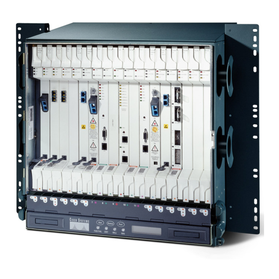
Cisco ONS 15454 Desembalagem e instalação - Página 31
Procurar online ou descarregar pdf Desembalagem e instalação para Servidor Cisco ONS 15454. Cisco ONS 15454 40 páginas. Four-shelf and zero-shelf bay assembly
Também para Cisco ONS 15454: Manual de instruções de instalação (22 páginas), Instalar (32 páginas), Instalar (32 páginas), Desembalagem e instalação (42 páginas)

Replace Side A or Side B of the FAP
When replacing Side A or Side B of the FAP, all wires must be disconnected from that module.
Note
Turn off the power supply to the side you are replacing, either Side A or Side B.
Step 1
Each side (Side A or Side B) has two power inputs. You must remove both power inputs from the side
Warning
you are replacing in order for that side to be powered down.
Disconnect the alarm wires on the module that is being replaced.
Step 2
Disconnect all wires from the input and output terminals on the side that is being replaced.
Step 3
Remove the four screws on the front and the four screws on the back of the side that is being replaced.
Step 4
Slide out the side that is being replaced from the FAP.
Step 5
Figure 31
Removing or Replacing FAP Side B
P O W
E R
A 1
LV D
A L A R
M
Slide in the new Side A or Side B and fasten it using the same eight screws (four front, four back) that
Step 6
were previously removed.
Step 7
Connect all wires from the output and input terminals on the new Side A or Side B.
Connect the alarm wires on the new Side A or Side B.
Step 8
Turn on the power to the new Side A or Side B.
Step 9
78-15720-04
W A R
N IN G
! D O
N O T
D IS C
R E M
O N N
E C T
O V E
IN G
M O D
P W E
U L E
R O N
B E F O
R E
R E A
R
5 0 A
M P M
A X P
E R F
1
U S E
A 1
2
P O W
E R
1
A 2
2
W A R
N IN G
A 2
! D O
D IS C
N O T
R E M
O N N
O V E
E C T
IN G
M O D
P W E
U L E
B E F O
R O N
P O W
R E A
R E
E R
R
LV D
A L A R
M
F U S
5 0 A
E
M P M
A L A R
A X P
M
E R F
B 1
1
U S E
B 1
2
P O W
1
B 2
2
LV D
A L A R
M
B 2
LV D
A L A R
F U S
E
A L A R
M
Unpacking and Installing the Cisco ONS 15454 Four-Shelf and Zero-Shelf Bay Assembly
Figure 31
E R
1 5 4 5
4 - F A
P - L V
D
M
Fuse and Alarm Panel Wiring
shows Side B being removed/replaced.
31
