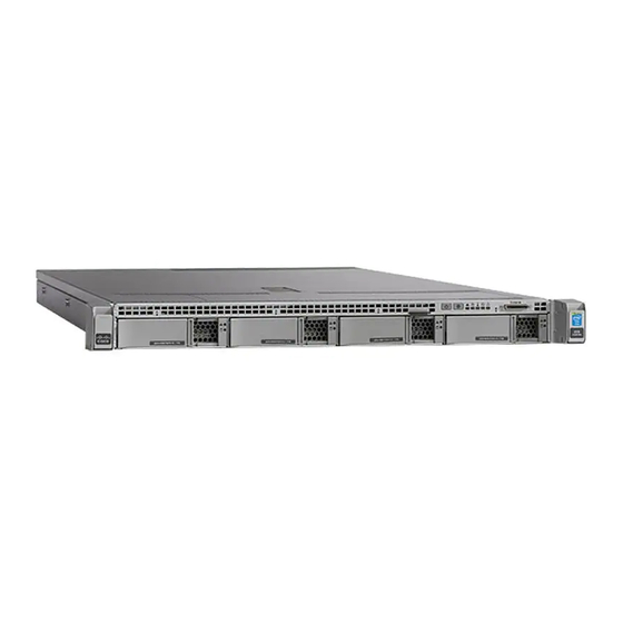
Cisco Firepower 1600 Manual de instalação do hardware - Página 38
Procurar online ou descarregar pdf Manual de instalação do hardware para Porta de entrada Cisco Firepower 1600. Cisco Firepower 1600 44 páginas.

Connect Cables, Turn on Power, and Verify Connectivity
3
5
7
Step 2
eth0 management interface (named 1)—Use this interface to perform initial setup using HTTPS, to perform routine
management, and to manage devices from the FMC chassis. Using an Ethernet cable, connect the eth0 interface to your
default management network reachable from your management PC. This interface is the default management interface
and is enabled by default.
Note
You must perform initial setup to change the eth0 IP address to match your network. You can use the
VGA/keyboard CLI for initial setup to set the eth0 IP address, or you can connect your computer directly to
eth0, change the address using the HTTPS initial setup, and then connect eth0 to your network.
Step 3
(Optional) eth1 management interface (named 6)—Connect this management interface to the same or different network
from your other management interfaces depending on your network needs. For information about management interfaces
and network topology, see the
Step 4
eth2 and eth3 management interfaces—If your model includes 10-Gigabit Ethernet SFP+ interfaces, install any
Cisco-supported SFP+ transceivers and cables as needed. You can connect these interfaces to the same or different network
from your other management interfaces depending on your network needs. For more information about management
interfaces and network topology, see the
Each Cisco-certified SFP+ transceiver (SFP-10G-SR) has an internal serial EEPROM that is encoded with security
information. This encoding allows us to identify and validate that the SFP transceiver meets the requirements for the
FMC chassis.
Note
Only Cisco certified SFP+ transceivers are compatible with the 10-G interfaces. Cisco TAC may refuse support
for any interoperability problems that result from using an untested third-party SFP transceiver.
Step 5
Power—Use one of the supported power cords to connect the power supplies of the chassis to your power source. For
more information about supported power cords, see
Step 6
Verify—Press the Power button on the front of the chassis, and verify that the power status LED is on.
Step 7
Setup and configuration—See the
and 4600
to continue setup and configuration.
Cisco Firepower Management Center 1600, 2600, and 4600 Hardware Installation Guide
34
Two USB 3.0 Type A ports
You can connect a keyboard, and along
with a monitor on the VGA port, you can
access the console.
eth1 management interface (named 2)
Gigabit Ethernet 100/1000/10000 Mbps
interface, RJ-45
Serial console port
Use the console cable (RJ-45 to DB-9) to
connect a computer to the FMC.
Firepower Management Center Configuration Guide
Firepower Management Center Configuration Guide
Cisco Firepower Management Center Getting Started Guide for Models 1600, 2600,
4
eth0 management interface (named 1)
Gigabit Ethernet 100/1000/10000 Mbps
interface, RJ-45
eth0 is the default management interface.
VGA video port (DB-15 connector)
6
This port is disabled by default; use the
VGA port and keyboard USB port instead.
Power Cord Specifications, on page
Mount and Connect
for your version.
for your version.
14.
