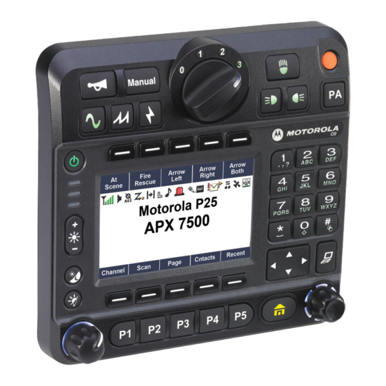
Motorola ASTRO APX O9 Manual de instalação - Página 9
Procurar online ou descarregar pdf Manual de instalação para Rádio Motorola ASTRO APX O9. Motorola ASTRO APX O9 25 páginas. Control head mobile radio
Também para Motorola ASTRO APX O9: Manual de referência rápida (44 páginas)

List of Figures
List of Figures
Mid Power Dash Mount Transceiver and Trunnion .............................................................. 1-1
Mid Power Dash Mount Transceiver and Trunnion ............................................................... 1-1
Figure 1-3. Front View of O3 Control Head with Coiled Cable................................................................ 1-1
Figure 1-4. Side View of O3 Control Head with Coiled Cable ................................................................. 1-1
Mid Power Dash Mount Transceiver and Trunnion ............................................................... 1-2
Dash Mount Transceiver and Trunnion ................................................................................. 1-2
and Trunnion ......................................................................................................................... 1-2
Figure 1-8. Side View of O7 Control Head Attached to APX 8500 Mid Power Dash Mount Transceiver and
Trunnion ................................................................................................................................ 1-2
Figure 1-9. Front View of Remote Mount and Trunnion .......................................................................... 1-2
Figure 1-10. Side View of Remote Mount and Trunnion ........................................................................... 1-2
Figure 1-11. Front View of O2 Control Head with Remote Mount and Trunnion....................................... 1-3
Figure 1-12. Side View of O2 Control Head with Remote Mount and Trunnion ........................................ 1-3
Figure 1-13. Front View of O5 Control Head with Remote Mount and Trunnion....................................... 1-3
Figure 1-14. Side View of O5 Control Head with Remote Mount and Trunnion ........................................ 1-3
Figure 1-15. Front View of O7 Control Head with Remote Mount and Trunnion....................................... 1-3
Figure 1-16. Side View of O7 Control Head with Remote Mount and Trunnion ........................................ 1-3
Figure 1-17. Front View of O9 Control Head with Trunnion ...................................................................... 1-4
Figure 1-18. Side View of O9 Control Head with Trunnion........................................................................ 1-4
Figure 1-19. Top View of O9 Universal Relay Controller with Trunnion (URC is an orderable accessory) 1-4
Figure 1-20. Side View of O9 UniversalRelay Controller with Trunnion(URC is an orderable accessory) 1-4
Figure 1-21. Siren and Lights Interface Module (SLIM) ............................................................................ 1-4
Figure 1-22. Front View of SB9600 Whelen Siren .................................................................................... 1-5
Figure 1-23. Siren/PA Cable Connections................................................................................................. 1-5
Figure 1-24. Dash Mount Configuration for O2 Control Head ................................................................... 1-6
Figure 1-25. Dash Mount Configuration for O3 Control Head ................................................................... 1-6
Figure 1-26. Dash Mount Configuration for O5 Control Head ................................................................... 1-7
Figure 1-27. Dash Mount Configuration for O7 Control Head ................................................................... 1-7
Figure 1-28. Remote Mount Configuration with Mid Power Transceiver, Transceiver Interface Board,
CHIB Rear Assembly and O2 Control Head ........................................................................ 1-8
Figure 1-29. Remote Mount Configuration with Mid Power Transceiver, Transceiver Interface Board and
O3 Control Head ................................................................................................................... 1-8
Figure 1-30. Remote Mount Configuration with Mid Power Transceiver, Transceiver Interface Board,
CHIB Rear Assembly and O5 Control Head ......................................................................... 1-9
Figure 1-31. Remote Mount Configuration with Mid Power Transceiver, Transceiver Interface Board, CHIB
Rear Assembly and O7 Control Head................................................................................... 1-9
Figure 1-32. Remote Mount Configuration with Mid Power Transceiver, Transceiver Interface Board and
O9 Control Head ................................................................................................................... 1-9
Figure 1-33. Remote Mount Configuration with Mid Power Radio Transceiver, Universal Relay Controller
and O7 Control Head (URC is optional).............................................................................. 1-10
Figure 1-34. Remote Mount Configuration with Mid Power Radio Transceiver, Universal Relay Controller
and O9 Control Head (URC is optional).............................................................................. 1-10
Figure 2-1. Dash Mount Radios Can Be Located in the Middle Console, on the Transmission Hump, or
Under the Dash..................................................................................................................... 2-2
MN003109A01
unt
unt
Mount and
Mount and
ntrol Head with
ntrol Head wi
Control Head with R
Cont
rol Head with
5 Control Head with Re
5 Control Head wit
Cont
Control Head with Remot
ad wit
ontrol Head with Re
ontrol Head with Remote M
rol Head with Remote Mou
with Rem
Head with Tr
ead w
ad with Trunnion...
ad with Trunnion..............
ay Controller with Trunnion
Controller with Trunnion
Controller with Trunnion(U
Controller with Trunnion
SLIM) ...........................
SLIM) ...............................
m
unnion
unnion ........
(
..............................
.................................
.........................
.......................
ead ...........
......
d ......
.....
vii
