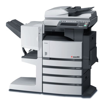
Toshiba E-STUDIO 232 Manual de serviço - Página 2
Procurar online ou descarregar pdf Manual de serviço para Impressora tudo em um Toshiba E-STUDIO 232. Toshiba E-STUDIO 232 20 páginas. Toshiba printer sales guide
Também para Toshiba E-STUDIO 232: Manual de vendas (48 páginas)

1. SPECIFICATIONS / ACCESSORIES / OPTIONS / SUPPLIES ................................... 1-1
1.1 Specifications....................................................................................................................... 1-1
1.2 Accessories ......................................................................................................................... 1-6
1.3 Options ................................................................................................................................ 1-7
1.3.1 e-STUDIO200L/230/230L/280/280S ........................................................................ 1-7
1.3.2 e-STUDIO202L/232/232S/282/282S ........................................................................ 1-8
1.4 Supplies ............................................................................................................................... 1-9
1.4.1 e-STUDIO200L/230/230L/280/280S ........................................................................ 1-9
1.4.2 e-STUDIO202L/232/232S/282/282S ........................................................................ 1-9
1.5 System List ........................................................................................................................ 1-10
1.5.1 e-STUDIO200L/230/230L/280/280S ...................................................................... 1-10
1.5.2 e-STUDIO202L/232/232S/282/282S ...................................................................... 1-16
2. OUTLINE OF THE MACHINE ....................................................................................... 2-1
2.1 Sectional View ..................................................................................................................... 2-1
2.2 Electric Parts Layout............................................................................................................ 2-4
2.3 Symbols and Functions of Various Components............................................................... 2-17
2.4 General Description ........................................................................................................... 2-26
2.4.1 System block diagram ............................................................................................ 2-26
2.4.2 Construction of boards ........................................................................................... 2-28
2.5 Installation and Replacement of Covers and PC Boards................................................... 2-30
2.5.1 Covers .................................................................................................................... 2-30
2.5.2 PC boards .............................................................................................................. 2-41
2.6 Installation and Replacement of Options ........................................................................... 2-51
3. COPY PROCESS .......................................................................................................... 3-1
3.1 General Description of Copying Process............................................................................. 3-1
3.2 Details of Copying Process.................................................................................................. 3-2
3.3 Comparison with e-STUDIO350/450 ................................................................................. 3-13
4. GENERAL OPERATION............................................................................................... 4-1
4.1 Overview of Operation ......................................................................................................... 4-1
4.2 Description of Operation ...................................................................................................... 4-2
4.2.1 Warming-up .............................................................................................................. 4-2
4.2.2 Ready state (ready for copying) ............................................................................... 4-2
4.2.3 Drawer feed copying (Upper drawer paper feeding) ................................................ 4-3
4.2.4 Bypass feed copying ................................................................................................ 4-5
4.2.5 Interruption copying .................................................................................................. 4-5
4.3 Detection of Abnormality...................................................................................................... 4-6
4.3.1 Types of abnormality ................................................................................................ 4-6
4.3.2 Description of abnormality ........................................................................................ 4-7
4.4 Flow Chart ......................................................................................................................... 4-12
4.4.1 Immediately after the power is turned ON .............................................................. 4-12
4.4.2 Automatic paper feed copying ................................................................................ 4-14
5. CONTROL PANEL........................................................................................................ 5-1
5.1 Control Panel and Display Panel ......................................................................................... 5-1
5.2 Items Shown on the Control Panel ...................................................................................... 5-2
5.2.1 Display...................................................................................................................... 5-3
5.3 Relation between the Equipment State and Operator's Operation...................................... 5-8
5.4 Description of Operation .................................................................................................... 5-12
5.4.1 Dot matrix LCD circuit ............................................................................................ 5-12
5.4.2 LED display circuit .................................................................................................. 5-15
5.5 Disassembly and Replacement ......................................................................................... 5-16
June 2004 © TOSHIBA TEC
CONTENTS
e-STUDIO200L/202L/230/232/280/282 CONTENTS
