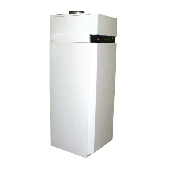
Dimplex AWP 30 HLW Manual de instruções de instalação e funcionamento - Página 6
Procurar online ou descarregar pdf Manual de instruções de instalação e funcionamento para Bomba de calor Dimplex AWP 30 HLW. Dimplex AWP 30 HLW 19 páginas. Hot water heat pump for indoor installation

Note → Heating element controller
The heating element controller is a second control unit for the op-
erating range of the electric heating element, and independent of
the hot-water controller. The factory setting for the switch-off
temperature is 65 °C. The heating element controller is com-
bined with the safety temperature limiter (see illustration).
If another temperature setpoint is required, ensure the controller
can only be accessed from above after removal of the front
panel. The heating element controller can be set to a max. value
of 85 °C (see also illustration in 3.3). This must be done by qual-
ified personnel only. Disconnect the power supply before open-
ing the unit!
3.5 "Heat Exchanger" Switch
Heat exchanger operation is to be used if DHW preparation is to
be executed with a second heat generator (e.g. by means of a
boiler or solar installation). The standard relay contact can be
used to load the hot-water cylinder via the integrated tube heat
exchanger, e.g. by means of pump or valve control.
Hot-water temperature is controlled using the hot-water heat
pump temperature controller.
Heat pump operation can be blocked as required if domestic hot
water is to be prepared using a second heat generator. This is
achieved by removing the factory-mounted copper bridge A2 (at
terminal strip X5, see Section 6.3) and integrating a floating con-
tact from the second heat generator regulation in the same posi-
tion. An external regulation must not lead to the maximum
switching frequency (12 operations/h) of the heat pump being ex-
ceeded. It may be necessary to take the local utility company
(EVU) specifications into consideration in this regard.
The electrical connection terminal to control (ON/OFF) the exter-
nal ancillary devices (pump, solenoid valve etc.) is located on the
control room panel.
This function is activated using the "heat exchanger" switch.
In addition, a vertical sensor pipe (∅
der at the rear of the hot-water heat pump (access via electrical
connection area). An external temperature sensor can be in-
serted here. There is a cable feedthrough at the rear of the unit.
www.dimplex.de
12 mm) is fitted to the cylin-
i
4
Storage / Transport
4.1 General Information
The hot-water heat pump should generally be stored and trans-
ported upright and empty. If handled carefully, the unit can be
transported over short distances with a max. tilt angle of 45°. Am-
bient temperatures between -20 and +70 °C are permissible dur-
ing transport and storage.
4.2 Fork-Lift Truck Transport
The hot-water heat pump must remain installed on the pallet dur-
ing transport. The pump should be lifted slowly. Because of its
high centre of mass, the hot-water heat pump must be secured
against canting.
Lowering the hot-water heat pump: To prevent damage, the hot-
water heat pump must be placed onto a level surface.
4.3 Manual Transport
Use the wooden pallet for manual transport. A second or third
carrying position can be determined with the help of ropes or car-
rying slings. If the pump is transported in this manner (or with a
sack barrow), do not, under any circumstances, exceed the max.
tilt angle of 45° (see illustration). If the pump can only be trans-
ported in a tilted position, it ("heat pump" switch) should not be
operated until at least one hour after installation in its final loca-
tion (see also Point 8).
ATTENTION!
The (painted) steel coverings, particularly the upper cover plates, are not
designed to withstand large forces!
ATTENTION!
High centre of mass, low overturning moment!
4.3
E-5
