DINA DN3PS2 Manual de instruções original - Página 7
Procurar online ou descarregar pdf Manual de instruções original para Interruptor DINA DN3PS2. DINA DN3PS2 12 páginas. Standstill monitoring for one and three phases motors without sensor system
Também para DINA DN3PS2: Manual de instruções original (16 páginas)

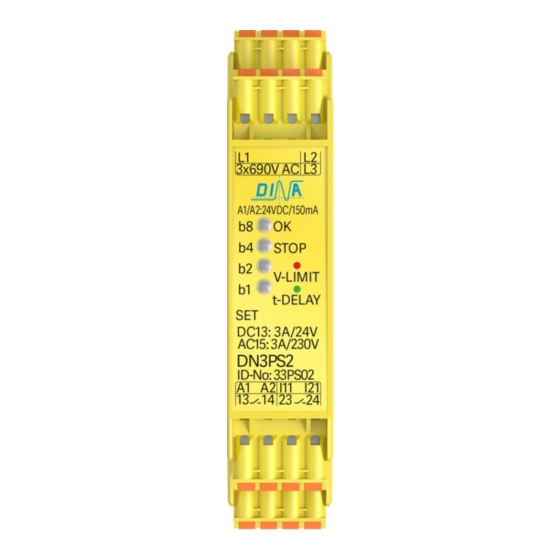
DN3PS2
Original Betriebsanleitung
Schaltschwelle Einstellung
• Gerät an die Betriebsspannung anschließen.
• Die Taste SET ca. 3s betätigt halten, bis alle LED rot
blinken.
• Nach der Betätigung blinken die LED rot entsprechend
der Binärkombination der aktuellen Parameterstufe
(Tabelle 2).
• Mit jeder kurzen Betätigung der SET Taste wird die
nächsthöhere Stufe zugewiesen.
• Durch Betätigen der SET Taste für ca. 2s wird der neue
Wert dauerhaft gespeichert und der Einstellmodus
verlassen.
Tabelle 2:
Einstellbereich der Stillstand Schaltschwelle
Tabelle 2
Position
Werteinstellung
LED: b8 / OK
Table 2 value
LED: b4 / STOP
adjustment
b2
b1
Kontakte aktiv Contacts on [mV] 50
Kontakte offen Contacts off [mV] 120 120 120 120 120 120
Einstellung der Einschaltverzögerungszeit
der Ausgangskontakte
• Gerät an die Betriebsspannung anschließen.
• Taste SET ca. 6s betätigen, bis alle LED grün blinken.
• Nach der Betätigung blinken die LED entsprechend
dem aktuellen Parameterwert (Tabelle 3).
• Jede kurze Betätigung erhöht den Wert eine Stufe.
• Betätigen für ca. 2s speichert den neu eingestellten
Wert.
• Betätigungstop ≥ 20s beenden die Einstellung.
• Alte Einstellung bleibt aktiv.
• Die Funktion bleibt während der Einstellung erhalten.
Tabelle 3
Position
Werteinstellung
LED: b8 / OK
Table 3 value
LED: b4 / STOP
adjustment
Verzögerung [s]
time delay [s]
DN3PS2
1
2
3
55
60
1
2
3
b2
b1
0,5
1
2
Stand: 29.09.2017
Original instruction manual
Switching value adjusting
• Connect the unit to the power supply.
• Activate button SET for approximately 3s.
• After the actuation the LED are flashing red according
to the binary combination of the actual parameters ad-
justment (table 2).
• The value of the parameters increases one step after
every short actuation of the button SET.
• To memorize the new value permanently and quit the
adjusting mode the button has to be actuated nearly
2s.
Table 2:
Adjustment range of the standstill switching value
4
5
6
7
8
65
70
75
80
200
120
1000 1000 1000 1000 1000 1000 1000 1000
Adjustment of the ON-delay time of the output
contacts
• Connect the unit to the power supply.
• Activate the button SET for ca. 6s till all LED are flashing
green.
• After the actuation the LED are flashing according to the
actual parameter (table 3).
• The parameter increases one step after every short ac-
tuation.
• Activation for 2s saves the new parameter.
• Activation stop ≥ 20s ends the configuration.
• Old parameter is active.
• The function is active during the configuration.
4
5
6
7
3
4
5
6
Seite 7 von 12
9
10
11
12
230
250
300
350
8
9
10
11
12
7
8
10
12
14
Date: 2017-09-29
13
14
15
400
460
500
13
14
15
16
18
20
Page 7 of 12
