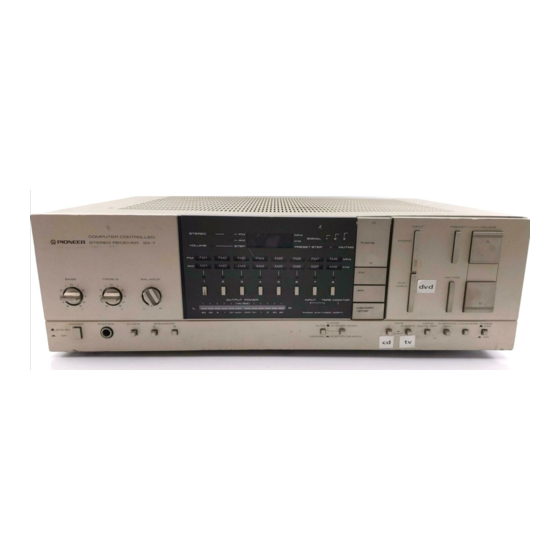
Pioneer SX-6 Manual de serviço - Página 11
Procurar online ou descarregar pdf Manual de serviço para Recetor Pioneer SX-6. Pioneer SX-6 15 páginas. Computer controlled stereo receiver
Também para Pioneer SX-6: Manual de serviço (25 páginas)

o Synthesizer Control
Fig. 1-5 outlines the tuner-related computer
operation command input key matrix.
Key description
9k/10k
: AM-MW band frequency step switch.
ON for 9kHz steps, and OFF for 10kHz
steps.
9k/1k (PD6004)
: AM-LW band frequency step
switching. ON for 9kHz steps, and OFF
for lkHz steps.
TUNING AUTO/MANUAL
: ON for auto tuning
(x1), and OFF for manual tuning.
SCAN/SEARCH : ON for short-time hold search
(x2), and OFF for operation according
to TUNING AUTO/MANUAL
switch
( * 6 ) .
FM
: Display of tuned frequency by single
push (*3), and pin 16 of synthesizer IC
(M54922P\ switched to L level (x4).
AM
: Display of tuned frequency by single
push (*3), and pin 16 of synthesizer IC
(M54922P) switched to H level (x{).
LW/MW (PD6004) : LW-MW switching with each
push.
M1 - M8 : T\rned frequency presetting keys. Cor-
responding STATION indicator lights
u p ( * 5 ) .
TUNING UP, DOWN : Frequency tuning keys.
MEMORY/STOP
:
Memory store enable key.
STATION indicators (1 to 8) and the
PRESET STEP indicator blinks on and
off for 5 seconds when pressed once.
A broadcasting station and volume step
may be stored in memory during this 5
second period.
And
when pressed
during frequency scanning, the scann-
ing operation is halted.
EL,E2
: Switching for different regions (USA,
Europe etc.) Wired up according to
region without switching.
81, B2 (PD6004) : FM IF offset adjustment.
(*1)
Station
search where frequencies are scanned by
pressing ?UN/NG
UP or DOWN key once. Scanning
stops when broadcast station frequency is tuned.
(*2)
Station scan where frequencies are also scanned by
pressing TUNING
UP or DOWN key once. Scanning
pauses for
5 seconds when broad,casting station
frequency is tuned. Scanning will be resumed after
the 5 second pause unless the MEMORY/STOP
hey
is pressed.
(*3)
16-bit serial d.ata from the SO pin is sent to the
frequency display d,riuer IC (TD6301P), conuerted
to 7-segment decimal data by transfer cloch (output
from Pg and P1 pins) for driuing the LED numeric
display.
LOCK SW.
NON-LOCK SW.
IlnAnjJ
Fig. 1-5
Switch key matrix for synthesizer control
(*4)
The data transfened to M54922P contains 2O bits.
These are diuided into 5 groups of 4 bits each by the
4 pins Rg to R1y
The transfer output
clock is
obtained from R6 and R7. The first 4 data items
(16 bits) are used in programmable diuider frequency
diuision, while the Sth data item (4 bifs) is used for
operation mode designation.
(*5)
BCD encoded data from
pins Og - Og is applied to
the BCD to decimal decoder IC (M74LS42P). Pins I
to 9 (excluding pin 8) correspond. to Ml
to M8, and
are switched to L leuel resulting in the LEDs being
lit up.
(*6)
Actual circuits are wired so that the K6 line to the
SCAN/SEARCH
switch
is cut
when the AUTO/
MANUAL
switch is in the MANUAL
position.
The
SCAN/SEARCH switch will be operatiue only when
in the AUTO position.
NON - LOCK SW.
