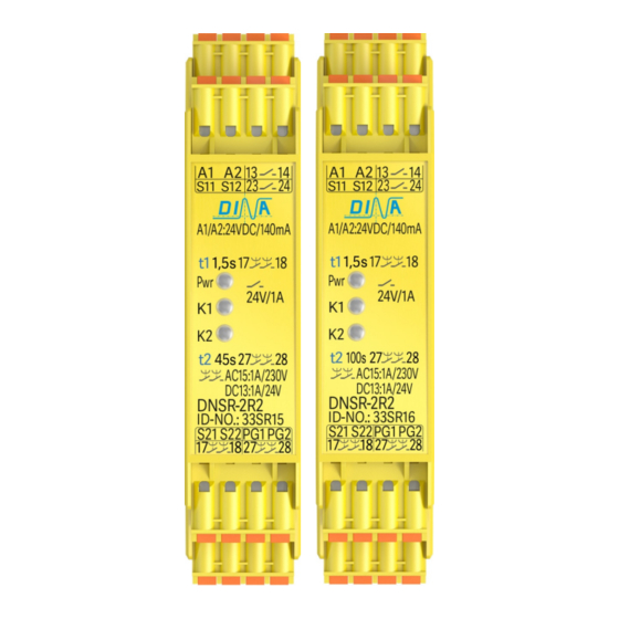
DINA Elektronik DNSR-2R2 Manual de instruções original - Página 8
Procurar online ou descarregar pdf Manual de instruções original para Instrumentos de medição DINA Elektronik DNSR-2R2. DINA Elektronik DNSR-2R2 16 páginas.

DNSR-2R2
Original Betriebsanleitung
Anschlussklemmen 33SR20
A1:
S11:
S12:
S21:
S22:
PG1/ PG2:
15
17
25
27
Produktbeschreibung 33SR20
• DNSR-2R2 verfügt über rückfall- und anzugs-
verzögerte Kontakte zur Freigabe von
Steuerstromkreisen.
• Der Anschlussplan ist am Gerät seitlich.
• Die steckbaren Klemmen sind Vertausch sicher.
• Durch Verbinden S11 mit S12 schließt der Kontakt
17-18 unverzögert und 15-16 öffnet.
• Durch Unterbrechen S11 von S12 öffnet 17-18
zeitverzögert und 15-16 schließt. LED K1 blinkt.
• Die Funktion ist nicht retriggerbar.
• Durch Verbinden S21 mit S22 schließt der
Kontakt 27-28 zeitverzögert und 25-26 öffnet.
LED K2 blinkt.
• Durch Unterbrechen S21 von S22 öffnet 27-28
unverzögert und 25-26 schließt.
Hinweis zu den Kontakten 15-16 und 25-26
• Diese sind (NO) Kontakte funktional invertiert zu den
Kontakten 17-18 und 27-28.
• Die Kontakte 15-16 und 25-26 sind ohne
Betriebsspannung offen und können nur unter
Spannung zur Quittierung verwendet werden.
Stand 30.08.2017
24V DC/ A2: 0V
Steuereingang, 15V DC±0,5V
für 15
16 und 17
Steuerspannung, 15V DC
Steuereingang, 12V DC±0,5V
für 25
26 und 27
Steuerspannung (12V DC)
Zeiteinstellungsfreigabe
für t1 und t2 über Drahtbrücke
16:
Diagnosekontakt,
anzugsverzögert (t1).
18: Sicherer Kontakt,
rückfallverzögert (t1)
26:
Diagnosekontakt,
rückfallverzögert (t2).
28: Sicherer Kontakt,
anzugsverzögert (t2)
Seite 8 von 16
Original Instruction Manual
Connection terminals 33SR20
A1:
S11:
18
S12:
S21:
28
S22:
PG1/ PG2:
15
17
25
27
Product description 33SR20
• DNSR-2R2 has OFF and ON time delayed
contacts to enable control circuits.
• The connection schematic is at the unit side t.
• The pluggable terminals are interchange safe.
• By connecting S11 to S12 the contact 17-18 closes
undelayed and the contact 15-16 opens.
• By disconnecting S11 of S12 17-18 opens
OFF-delayed and 15-16 closes. LED K1 is flashing.
• The function is not retrigger able.
• By connecting S21 to S22 the contact 27-28
closes ON-delayed and 25-26 opens. LED K2 is
flashing.
• By disconnecting S21 to S22 the contact 27-28
opens undelayed and 25-26 closes.
Remark to the contacts 15-16 and 25-26
• These are NO contacts functional inverted to the
contacts 17-18 and 27-28.
• The contacts 15-16 and 25-26 are open without power
supply. They can be used for quit function only during
power on.
Date 2017-08-30
24V DC/ A2: 0V
Control input, 15V DC±0,5V
for 15
16 and 17
Control voltage, 15V DC
Control input, 12V DC±0,5V
for 25
26 and 27
Control voltage, 12V DC
Time adjustment enabling for
t1 and t2 via wire connection
16:
Diagnostics contact
ON-delayed (t1).
18: Safe contact
OFF-delayed (t1)
26:
Diagnostics contact
OFF-delayed (t2).
28: Safe contact
ON-delayed (t2)
Page 8 of 16
18
28
