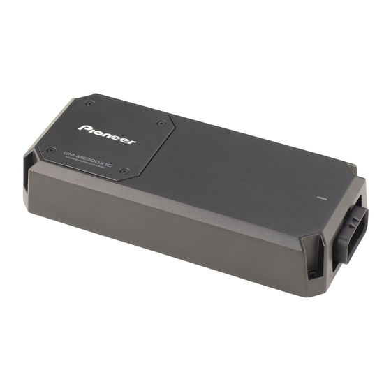
Pioneer GM-ME300X1C Manual do Proprietário - Página 8
Procurar online ou descarregar pdf Manual do Proprietário para Amplificador Pioneer GM-ME300X1C. Pioneer GM-ME300X1C 13 páginas. Marine mono amplifier

If you lose the supplied tool, use a flat screw-
driver with a tip width of 3 mm or less as a
substitute.
Max 3 mm (1/8 in.)
Connections when using the
speaker input wire
Connect the headunit speaker output wires to
the amplifier using the supplied speaker input
wire with RCA pin cord.
Make sure to switch the INPUT SENS switch
to SP.
1 Headunit
2 Speaker output
3 Red: Right
4 Black: Right
5 Black: Left
6 White: Left
7 Speaker input wire with RCA pin cord
to the RCA input jack of this unit
Note
If speaker input wires from a headunit are
connected to this amplifier, the amplifier will
automatically turn on when the headunit is
turned on. When the headunit is turned off,
the amplifier turns off automatically. This
function may not work with some headunits.
In such cases, make sure that the L channel
is connected correctly. If the function still
does not work, please use a system remote
control wire (sold separately). If multiple
amplifiers are to be connected together
synchronously, connect the headunit and all
amplifiers via the system remote control wire.
Installation
Before installing the
WARNING
To ensure proper installation, use the sup-
plied parts in the manner specified. If any
parts other than those supplied are used, they
may damage internal parts of the amplifier or
become loose, causing the amplifier to shut
down.
Do not install:
— On surfaces that could become loose
if the boat stops suddenly (chassis
recommended).
— In places where it may interfere with the
boat's operation.
Install tapping screws in such a way that the
screw tip does not touch any wire. This is
important to prevent wires from being cut by
vibration of the boat, which can result in fire.
Make sure that wires do not get caught in
the sliding mechanism or touch the legs of a
person in the boat as short-circuit may result.
CAUTION
Place all cables away from hot places, such
as near the heater outlet.
The optimal installation location differs
depending on the boat model. Secure the
amplifier at a sufficiently rigid location.
Check all connections and systems before
final installation.
Example of installation on
the chassis
installation location.
Insert the supplied tapping screws (4 mm
× 25 mm) into the screw holes and push
on the screws with a screwdriver so they
make an imprint where the installation
holes are to be located.
2
Drill 2.5 mm (1/8 in.) diameter holes in
the mounting surface.
En(7/9)
