Pioneer GM-X544 Manual do Proprietário
Procurar online ou descarregar pdf Manual do Proprietário para Amplificador Pioneer GM-X544. Pioneer GM-X544 6 páginas. Bridgeable four-channel power amplifier
Também para Pioneer GM-X544: Manual do Proprietário (13 páginas), Manual de serviço (28 páginas)
BRIDGEABLE FOUR-CHANNEL
POWER AMPLIFIER
AMPLIFICADOR DE POTENCIA DE
CUATRO CANALES EN PUENTE
Owner's Manual
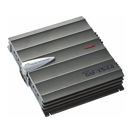
GM-X544
Manual del Propietario
PIONEER CORPORATION
4-1, MEGURO 1-CHOME, MEGURO-KU, TOKYO 153-8654, JAPAN
PIONEER ELECTRONICS (USA) INC.
P.O. Box 1760, Long Beach, California 90801, U.S.A.
TEL: (800) 421-1404
PIONEER ELECTRONIC (EUROPE) N.V.
Haven 1087 Keetberglaan 1, 9120 Melsele, Belgium
TEL: (0) 3/570.05.11
PIONEER ELECTRONICS AUSTRALIA PTY. LTD.
178-184 Boundary Road, Braeside, Victoria 3195, Australia
TEL: (03) 9586-6300
PIONEER ELECTRONICS OF CANADA, INC.
300 Allstate Parkway, Markham, Ontario L3R 0P2, Canada
Published by Pioneer Corporation.
TEL: (905) 479-4411
Copyright © 2000 by Pioneer Corporation.
PIONEER ELECTRONICS DE MEXICO, S.A. de C.V.
All rights reserved.
San Lorenzo Num 1009 3er piso Desp. 302
Publicado por Pioneer Corporation.
Col. Del Valle, Mexico D.F. C.P. 03100
Copyright © 2000 Pioneer Corporation.
TEL: 5-688-52-90
Todos los derechos reservados.
Printed in U.S.A.
Impreso en los EE.UU.
<00A00F0R01>
<HRD0134-A> ES
Before Using This Product
Thank you for purchasing this PIONEER
product. Before attempting operation, be
sure to read this manual.
In case of trouble
When the unit does not operate properly,
contact your dealer or the nearest autho-
rized PIONEER Service Station.
WARNING
• Always use the special red battery and ground
wire [RD-223], which is sold separately. Connect
the battery wire directly to the car battery positive
terminal (+) and the ground wire to the car body.
• Do not touch the amplifier with wet hands.
Otherwise you may get an electric shock. Also, do
not touch the amplifier when it is wet.
• For traffic safety and to maintain safe driving
conditions, keep the volume low enough so that
you can still hear normal traffic sound.
• Check the connections of the power supply and
speakers if the fuse of the separately sold battery
wire or the amplifier fuse blows. Detect the cause
and solve the problem, then replace the fuse with
another one of the same size and rating.
• To prevent malfunction of the amplifier and
speakers, the protective circuit will cut the power
supply to the amplifier (sound will stop) when an
abnormal condition occurs. In such a case, switch
the power to the system OFF and check the
connection of the power supply and speakers.
Detect the cause and solve the problem.
• Contact the dealer if you cannot detect the cause.
• To prevent an electric shock or short-circuit
during connection and installation, be sure to
disconnect the negative (–) terminal of the battery
beforehand.
• Confirm that no parts are behind the panel when
drilling a hole for installation of the amplifier. Be
sure to protect all cables and important equipment
such as fuel lines, brake lines and the electrical
wiring from damage.
Setting the Unit
Gain Control
Adjusting the gain controls A and B will
help match the output of the car stereo to
the Pioneer amplifier. Normally, set the
gain controls to the "NORMAL" posi-
tion. If the output is low, even when the
volume of the car stereo is turned up,
turn these controls clockwise. If there is
distortion when the volume of the car
stereo is turned up, turn these controls
counter-clockwise.
• If you only use one input plug, set the gain
controls for speaker outputs A and B to the
same position.
• When using with an RCA equipped car
stereo (standard output of 500 mV), set to
the NORMAL position. When using with
an RCA equipped Pioneer car stereo with
max. output of 4 V or more, adjust level to
match the car stereo output level.
• If you hear too much noise when using the
speaker input terminals, turn the gain
control counter-clockwise.
Input Select Switch
For two-channel input, slide this switch
to the left. For four-channel input, slide
this switch to the right.
Cut Off Frequency Control
If the LPF/HPF select switch is set to
LPF or HPF, you can select a cut off fre-
quency from 40 to 120 Hz.
Power Indicator
The power indicator lights when the
power is switched on.
BFC (Beat Frequency Control) Switch
If you hear a beat while listening to an
AM broadcast with your car stereo,
change the BFC switch using a small
standard tip screwdriver.
LPF (Low-Pass Filter)/HPF (High-Pass Filter) Select Switch
Set the LPF/HPF select switch as follows according to the type of
speaker that is connected to the speaker output connector and the car
stereo system:
LPF/HPF Select
Audio frequency range
Speaker
Remarks
Switch
to be output
Type
LPF (Left)
* — 40 to 120 Hz
Subwoofer
Connect a subwoofer.
OFF (Center)
Full range
Full range
HPF (Right)
* 40 to 120 Hz —
Full range
Use if you want to cut the
very low frequency range*
because it is not necessary
for the speakers you are
using.
* See the "Cut Off Frequency Control" section.