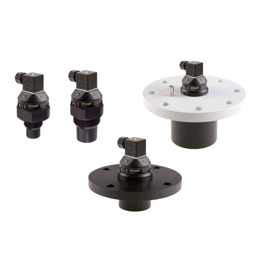
Dinel ULM-53 series Manual - Página 5
Procurar online ou descarregar pdf Manual para Nível laser Dinel ULM-53 series. Dinel ULM-53 series 6 páginas. Ultrasonic level meters
Também para Dinel ULM-53 series: Manual de instruções (20 páginas), Manual de instruções (20 páginas), Manual (8 páginas)

E
LECTRICAL CONNECTION
The ultrasonic level meter is designed to be con-
nected to supply unit or to controller through two or
three-wire cable with outer diameter 6 ÷ 8 mm (rec-
ommended cross section of cores 0,5 to 0,75 mm
by means of connector which is included in delivery.
Connection diagram and inner view of the connector
as shown in picture. Always disconnect the power
supply before connecting the level meter electrically!
Note: In case of strong electromagnetic interferences
(EMI), parallel cable ducting with power lines, or when
cable length exceeds 30 m we recommended to use
shielded cable.
WARNING:
With regard to possible occurrence of electrostatic
charge on non-conductive parts of the level meter, me-
tallic fl anges of the ULM-53Xi-10-I and ULM-53Xi-20-I
(for explosive areas) level meters must be grounded
with ground terminal!
L
EVEL METER SETTING
The measuring range is setup by means of two buttons "DOWN"
and "UP".The "DOWN" button is used to enter to the setting mode
(setting the 4 mA or 0 V limit) and to decrease the output current
or voltage. The "UP" button as an opposite function (setting the
20 mA or 10 V limit and increasing the output current or voltage).
Values are confi rmed by simultaneous pressing of both buttons for
about 1 sec. The setting process is indicated by yellow "MENU"
LED indicator.
For detailed information please read at the instructions manual.
S
TATUS AND FAILURE SIGNALIZATION
LED indicators
colour
"STATE"
green
"MENU"
yellow
R
ANGE OF APPLICATION
For continuous non-contact level measurement of liquids (water solutions, sewerage water, etc.), mash and paste materials (sedi-
ments, sticks, resins etc.) in closed or open vessels, sumps, reservoirs and open channels.
In case the level of bulk-solid materials is measured, the measurement range is reduced. We recommend to consult the use with
the manufacturer.
2
)
function
Slow flashing
(1–2 sec. depends on the measuring interval) – reception of refl ected signal (echo) from the measured
level. Correct function.
Fast blinks
– the measured value is in "dead zone" of the level meter, or the ultrasonic transm. is polluted.
Dark
– the measured value is in "dead zone" of the level meter, or the ultrasonic transm. is polluted. Incorrect
installation or malfunction.
Slow blinks
– signalization setting limit 4 mA
Fast blinks
– signalization setting limit 20 mA
Connection scheme
coments:
bk – black
bn – brown
bu – blue
NC – not connected
connector
ultrasonic transmitter
Full view of ultrasonic level meter
0V
(bu)
+U
(bn)
(bu)
(bk)
0V
U
out
+U
(bn)
The inside of the
connector socket
button "DOWN"
button "UP"
LED indicator "MENU"
LED indicator "STATE"
ULM-53-dat-5.6
