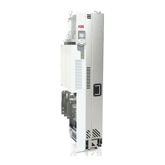
ABB ACQ580-04 Manual de instalação rápida - Página 11
Procurar online ou descarregar pdf Manual de instalação rápida para Unidade de controlo ABB ACQ580-04. ABB ACQ580-04 20 páginas. Converter modules with electrolytic dc capacitors in the dc link
Também para ABB ACQ580-04: Manual (16 páginas)

Check the insulation of the input and motor cables and
the motor
Check the insulation of the input cable according to local regulations before you connect it
to the drive.
See figure
H
on page 16. Ground the motor cable shield at the motor end. For minimal
interference, make a 360-degree grounding at the cable lead-through, or keep the pig tail
short.
Check the insulation of the motor and motor cable when the motor cable is disconnected
from the drive, see figure
phase conductor and then between each phase conductor and the Protective Earth
conductor using a measuring voltage of 1000 V DC. The insulation resistance of an ABB
motor must exceed 100 Mohm (reference value at 25 °C or 77 °F). For the insulation
resistance of other motors, consult the manufacturer's instructions. Note: Moisture inside
the motor casing will reduce the insulation resistance. If you suspect moisture, dry the
motor and repeat the measurement.
Connect the power cables (and install the shrouds for
option +B051)
See figure
G
on page 16.
Step
1
Install the grounding terminal to the drive module base.
2
Run the motor cables to the cabinet. Ground the cable shields 360 degrees at
the cabinet lead-through.
3
Connect the twisted shields of the motor cables to the grounding terminal.
4
Screw in and tighten the insulators to the drive module by hand. Install the
T3/W2 connection terminal to the insulators.
WARNING! Do not use longer screws or bigger tightening
torque than given in the installation drawing. They can damage
the insulator and cause dangerous voltage to be present at the
module frame.
5
Connect the phase conductors to the T3/W2 terminal.
6
Install the T2/V2 connection terminal to the insulators. See the warning in step 4.
7
Connect the phase conductors to the T2/V2 connection terminal.
8
Install the T1/U2 connection terminal to the insulators. See the warning in step 4.
9
Connect the phase conductors to the T1/U2 terminal.
10
For option +B051 (if there is no bottom plate in the cabinet and degree of
protection of IP20 is needed):
• Step drill carefully sufficiently big holes to the inner clear plastic shrouds for the
motor cables to the connected. Smooth the hole edges. Cut the shroud from the
holes to the edge to make it possible to put the shroud around the cables.
• Remove the plastic sheeting from the shrouds from both sides.
11
For option +B051: Put the inner clear plastic shrouds of figure
motor cables.
12
For option +B051: Remove the plastic sheeting from the output clear plastic
shroud from both sides. Install the shroud to the drive module.
13
For option +B051: Install the lower front cover to the drive module.
I
on page 16. Measure the insulation resistance between each
Task (motor cables)
EN – Quick installation guide 11
Figure
J
K
L
M
N
-
-
-
-
O
O
around the
P
Q
Q
EN
DE
ES
FI
FR
Page
FR
16
16
IT
16
16
FR
PL
16
PT
-
-
RU
-
-
17
SV
TR
ZH
17
17
17
