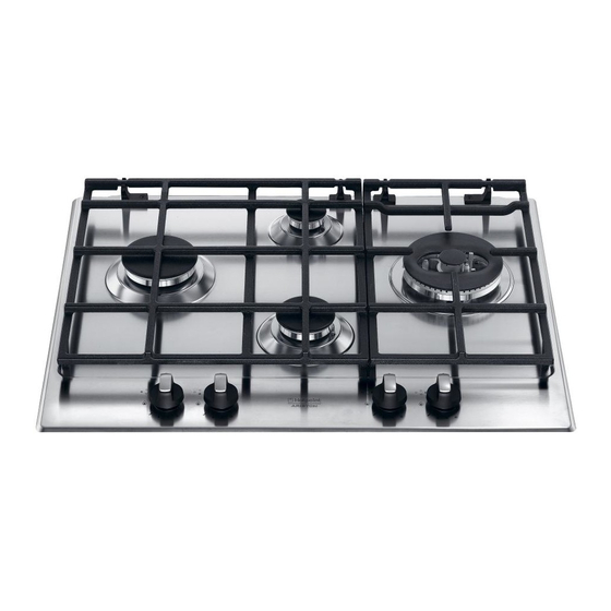
Ariston PK 640 R GH AUS Manual de Instruções - Página 7
Procurar online ou descarregar pdf Manual de Instruções para Hob Ariston PK 640 R GH AUS. Ariston PK 640 R GH AUS 32 páginas.
Também para Ariston PK 640 R GH AUS: Manual de Instruções (44 páginas)

Installation
! Before operating your new appliance please read this
instruction booklet carefully. It contains important information
for safe use, installation and care of the appliance.
! Please keep these operating instructions for future
reference. Pass them on to possible new owners of the
appliance.
Compliance with standards
This cooktop must be installed by an authorised person in
accordance with the requirements of local gas and electrical
authorities, as well as the latest published versions of the
following standards:
• AS/NZS 5601 Gas installation and pipe sizing
• SAA Wiring Rules.
Positioning
! Keep packaging material out of the reach of children. It can
become a choking or suffocation hazard (see Precautions
and tips).
! The appliance must be installed by a qualified and
authorised professional according to the instructions
provided. Incorrect installation may cause harm to people
and animals or may damage property.
Kitchen Ventilation
Where the total input of all appliances exceeds 3 MJ/h for
each cubic metre of the room or enclosure volume, the
space shall be ventilated by one of the methods detailed
below. For the purpose of assessing the adequacy of
ventilation, the space that cannot be isolated by doors is
the 'volume of a room'.
Natural ventilation direct from outside
Two permanent openings shall be provided directly to
outside. The openings shall be located to ensure the
distance between the top of the upper opening and the
ceiling of the room or enclosure, and the distance between
the bottom of the lower opening and the floor of the room
or enclosure does not exceed 5% of the height of the room
or enclosure. The minimum free ventilation area provided
by each opening shall be calculated using the following
formula:
A = 3 × T
where
A = the minimum free ventilation area (cm
T = the total gas consumption of all appliances (MJ/h)
The minimum vertical dimension of any free ventilation
opening shall be 6 mm.
NOTE 1 When used in this Clause, the term 'directly to
outside' means any one of the following options, provided
that the ventilation path is unobstructed by building material
or insulation:
(a) Directly through an outside wall (preferred option).
(b) Through to an outside wall but offset.
(c) Into a cavity ventilated to outside.
(d) Into an under floor space ventilated to outside.
(e) Into a roof space ventilated to outside.
NOTE 2 The two openings may be combined provided that
the top and bottom of the opening reach the limits set by
this Clause.
Natural ventilation via adjacent room
Two permanent openings shall be provided in the room
or enclosure. The openings shall be located to ensure the
distance between the top of the upper opening and the
ceiling of the room or enclosure, and the distance between
the bottom of the lower opening and the floor of the room
or enclosure does not exceed 5% of the height of the room
or enclosure.
The minimum free ventilation area provided by each opening
shall be calculated using the following formula:
A = 6 × T
where
A = the minimum free ventilation area (cm
T = the total gas consumption of all appliances (MJ/h)
These requirements shall apply to all subsequent rooms
until a room is ventilated to outside, in accordance with the
previous section, or the total input of the appliances does
not exceed 3 MJ/h for each cubic metre of the total volume
of the enclosure and rooms.
The minimum vertical dimension of any free ventilation
opening shall be 6 mm.
NOTE: The two openings may be combined provided that
the top and bottom of the opening reach the limits set by
this Clause.
• Liquid petroleum gas sinks to the floor as it is heavier
than air. Therefore, rooms containing LPG cylinders must
also be equipped with vents to allow gas to escape in
the event of a leak. As a result LPG cylinders, whether
partially or completely full, must not be installed or stored
in rooms or storage areas that are below ground level
(cellars, etc.). It is advisable to keep only the cylinder
being used in the room, positioned so that it is not subject
to heat produced by external sources (ovens, fireplaces,
stoves, etc. ) which could raise the temperature of the
cylinder above 50°C.
Adjacent cabinetry
The location of connection points is given in the table on
page 5 . For trouble-free operation of appliances installed in
housing units, the minimum distances shown in fig.4 should
be observed. It is recommended that the adjacent kitchen
surfaces should be capable of withstanding temperatures
)
2
of 65°C. Also, the following must be observed:
• The appliance should be installed next to cabinetry which
is no taller than the top of the cooker hob.
• The wall in direct contact with the back panel of the
cooker must be made of non-flammable material.
During operation of the cooker, the back panel of the
cooker could reach a temperature of 50°C above room
temperature.
• Kitchen cabinets installed next to the cooker that are
higher than the top of the hob, must be at least 600 mm
from the edge of the hob itself.
• If the hood is installed below a wall cabinet, the latter
must be at least 700 mm (millimetres) above the surface
of the hob.
AUS
)
2
7
