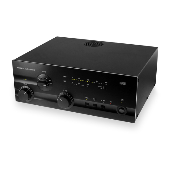
Acom 1011 Manual de instruções - Página 8
Procurar online ou descarregar pdf Manual de instruções para Amplificador linear Acom 1011. Acom 1011 19 páginas. Hf linear amplifier

a) Connect the station's grounding system to the wing-nut ground stud of the amplifier (on the rear
panel, marked GND in Fig. 2-1).
b) Connect a suitable coaxial cable between the transceiver output to the amplifier (rear panel) RF
INPUT SO-239 connector, using PL-259 connector.
The coaxial cable from the amplifier's output must be capable of handling the
amplifier's output power safely, particularly on the 10-meter band. It is suggested
that, at a minimum, RG8X (including RG8MINI, RK50-4-11, RK50-4-13) or, even
better, RG213 (including RK50-7-11) coaxial cable be used.
c) Connect a suitable coaxial cable from the antenna to the appropriate amplifier output (on the rear
panel, marked ANT1 or ANT2), using a PL-259 plug.
d)
Run a shielded cable from the "ground on transmit" socket or terminal on your transceiver to
the amplifier rear panel KEY-IN socket. The KEY-IN socket uses a standard RCA phono plug.
Your amplifier will not work if KEY-IN is not connected properly.
Transceiver producers assign different names to their "ground on transmit" output terminals, e.g., TX-
GND, SEND, T/R-LINE, etc. Some transceivers may require that "ground on transmit" be implemented
by a software command, or by changing the setting of a switch on the rear panel or inside the transceiver.
Check your transceiver's manual for more information on keying amplifiers.
e) Preparation of the wall outlet for the amplifier.
FUSE 5x20
FUSES
DANGER! HIGH VOLTAGE INSIDE !
100-120V: 10A
200-240V 6.3A
FOLLOW INSTRUCTIONS PRECISELY
DISCONNECT AC POWER
BEFORE REMOVING COVER !
100-120 or 200-240 V
50-60 Hz 1200 VA
RF INPUT
KEY IN
GND
a
d
Fig. 2-1 Connections
MODEL: ACOM 1011
SERIAL NO.:
FCC ID:
ANT 1
ANT 2
MADE IN BULGARIA
b
CAUTION
NOTE
c
7
