FirePro FPC-2 Manual de operação e manutenção - Página 8
Procurar online ou descarregar pdf Manual de operação e manutenção para Controlador FirePro FPC-2. FirePro FPC-2 8 páginas. Fire control panel system isolation
Também para FirePro FPC-2: Manual de operação e manutenção (7 páginas), Manual de operação e instalação (14 páginas), Manual de início rápido (2 páginas)

8.
Commissioning & Testing
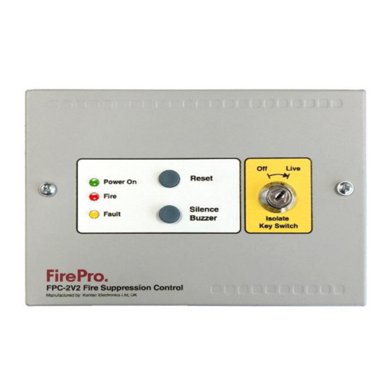
ISOLATE SYSTEM
Turn Key-Switch to "Off"
Requires 003 Key
This will create a fault on the Panel.
TO TEST SYSTEM:
1
Isolate system – t urn Key-Switch to "Off".
2
Turn Power off.
3
Disconnect FirePro units and connect test lamps or Test
Modules.
4
Visually inspect each FirePro unit installed and ensure Bracket
and mounting bolts are secure. The FirePro® unit must be
clean and free of debris.
5
Inspect all other component detectors, sirens etc. Inspect cable
for any signs of damage.
6
Turn power on to panel and turn to "live" test detection system
to simulate activation-all test lamps to be lit.
7
Turn off power Isolate system – Reconnect all FirePro units.
8
Turn Power on - Turn system back to Live.
If connecting FP-08800 Test Simulator – Then MUST USE V4 of the
test simulator, or the fuse will blow on EACH test.
Note: If the system has been activated the system activation fuse needs to be inspected as blown fuse
will show as a fault. The Fuse is 1.6AMP Quick Blow.
9.
Specifications
Mains supply
Mains supply fuse
Operating Voltage
Output voltage
Standby Current
Extinguishant release output
Low Voltage limit
Extinguishant release
Extinguishant release duration
Detection Type
Detection Circuit End of Line
Fault relay contact rating
Fire relay contact rating
Cable Entries
Terminal capacity
Construction
OPERATIONAL
24V DC +10% - 15%
1.6Amp (Quick Blow)
19-30V DC
19-30V DC +/- 2%
18mA
19 to 30V DC. Fused at 1.6 Amp
6V DC – at this point unit is operational will send fault signal to Sigma XT Panel
Immediate – Max 4 FirePro Aerosol units
Latched - Continuous
Hochiki Conventional PE smoke or Thermal Detectors – Max of 2 Detectors, can be mixed.
Linear Heat Detection Cable - Latching Type NO – LHD Cable Max 30m
6K8 5% ½ Watt resistor
30VDC 1A Amp max
30VDC 1A Amp max
8 x21mm knockouts provided
0.5mm
2
to 2.5mm
2
solid or stranded wire
1.2mm steel – Epoxy Powder Coated
Fire Control Panel
FP-C2
ISOLATED
Rev 7.0
Page | 8
