Fireray 5000 Manual do utilizador - Página 4
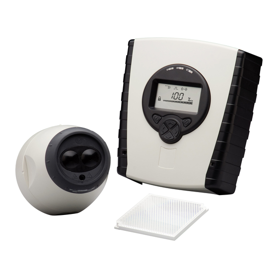
Procurar online ou descarregar pdf Manual do utilizador para Alarme de fumo Fireray 5000. Fireray 5000 17 páginas. Motorised infrared optical beam smoke detector

3. Wiring Diagrams
Wiring two Detectors onto two Zones:
To Detector 1
DET 1
N/O
Zone 1 -
Zone 1 +
Ext Reset
Supply +
Supply -
Zone 2 +
Zone 2 -
• Note 1: This component is the fire resistor. Its value is specified by the Fire Control Panel
manufacturer. For U.S. installations it is typically a short circuit
• ALWAYS use a separate 2-core cable for each Detector head
• CAUTION: For system monitoring - Do not use looped wire under any terminals. Break wire
run to provide monitoring of connections
• Components not supplied:
• End Of Line ('EOL') component - supplied by Fire Control Panel manufacturer
• Fire Resistor
• After installation, check operation of Fire and Fault connection on Fire Panel
• Apply a voltage of 5V to 40V to 'Ext Reset' contact for at least 2 seconds to clear a latched
fire condition
To Detector 2
DET 2
Fire
Con A
1
2
3
COM
N/C
N/O
see
note 1
EOL
EOL
see
note 1
N/O
COM
N/C
1
2
3
Con C
Fire
Fault
Con B
1
2
3
COM
N/C
4
N/O
COM
N/C
1
2
3
Con D
Fault
14V - 36V DC
Ext
Reset
