CALECTRO CFA-24V Instruções de instalação - Página 2
Procurar online ou descarregar pdf Instruções de instalação para Sistema de segurança CALECTRO CFA-24V. CALECTRO CFA-24V 4 páginas. Freeze protection alarm

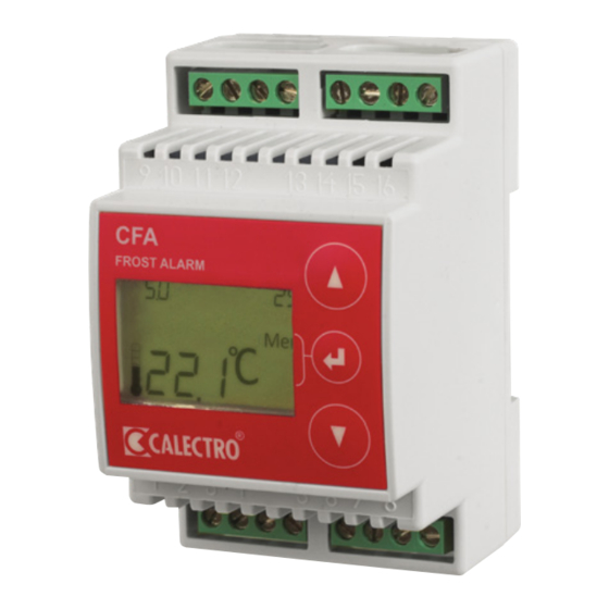
6. BUTTONS AND MENU SYSTEM
▲ = Step up in the menu / increase value - Keep
the button depressed and the setpoint counts up
rapidly.
▼ = Step down in the menu / decrease value -
Keep the button depressed and the setpoint
counts down rapidly.
= Is a multifunction button, the current status*
of which is shown on the display next to the but-
ton.
* Middle button functions:
• Exit Menu = Exit the menu / Save setting
• Menu = Enter the menu or select application
• Enter = Confirm setting
• Reset = Resets the relay after an alarm.
Exit
Menu
Enter
Reset
The menu system comprises of the following
sub-menus:
1. Selection of temperature sensor
2. Fine-adjustment of the temperature
measurement
4. Selection of output signal: 0-10 or 10-0V
5. Exit the menu system
7.
SELECTION OF TEMPERATURE
SENSOR
CFA can be connected to a range of temperature
sensors: Pt100, Pt1000, Ni1000 plus Calectros
NTC and PTC sensors in the ETF series. Pt1000
is a factory set sensor.
2. Press the Menu button (
menu system
3. The current type of temperature sensor is
shown
4. Press Menu-Enter to change the tempera-
ture sensor type
5. The current sensor type begins to blink and
you can now use the arrow buttons to select
another sensor type. Press Enter to confirm
your selection.
6. Use the arrow keys and confirm Exit-Menu
to exit
8. SETTING THE ALARM TEMPERATURE
AND HEAT RETENSION SETPOINT
To change the alarm temperature, press ▲ or
▼ to the desired value. The alarm temperature,
which is shown in the top left-hand corner, blinks
during setting. Press Enter to confirm (
C
°
Enter
DI
The setpoint for warming function (night mode),
which is shown in the display's top right-hand corner,
now begins to blink. Use ▲ to ▼ change to desired
value and press Enter to confirm (
These settings can also be changed during an alarm.
9.
RESETTING THE ALARM
When the alarm triggers, the relays remain in alarm
mode until the reset button is pressed.
Freeze alarm in daytime mode
Alarm
Freeze alarm in night mode
Alarm
If the alarm mode returns to normal temperature
when the Reset button is pressed, the relays are
reset and the middle button returns to the Menu
function.
) to enter the
If the alarm is still triggered after the Reset button is
pressed, the relays have not been reset and Alarm
and Reset blink three times. The middle button then
returns to the Menu function for 20 seconds to allow
settings to be changed in the menu system before
returning to Reset.
Reset depressed in alarm mode (daytime mode)
Alarm
Reset depressed in alarm mode (night mode)
).
Alarm
). Ready!
C
°
Enter
DI
C
°
Reset
DI
1 2
C
°
Reset
1 2
C
°
Reset
DI
1 2
C
°
Reset
1 2
The alarm temperature and warming function
setpoint can always be adjusted, even during
alarm mode. See 8.
10. FINE ADJUSTMENT OF THE
TEMPERATURE MEASUREMENT
The temperature measurement in CFA can be
adjusted if necessary. Range: -3°C to +3°C in
steps of 0.1°C.
1. Press the Menu button (
menu system
2. Press the arrow key until 'Adj' shows on the
display
3. Press Menu-Enter to adjust
4. The current compensation and temperature
starts to blink and you can now adjust the
compensation using the arrow keys. Press
Enter to confirm your selection (
5. Use the arrow keys and confirm Exit-Menu
to exit
11. DISPLAY EXAMPLE
The below example shows CFA in daytime
mode. The freeze alarm has triggered.
Daytime mode: 4°C
Alarm temperature
p-band
Alarm mode
Alarm
C
°
Reset
DI
1 2
Both relays have
been deactivated =
Digital inlet
alarm mode
short circuited = daytime mode
The below example shows CFA in night mode
/ warming function. The freeze alarm has trig-
gered.
Night mode/
Alarm temperature
warming function
Alarm mode
Alarm
C
°
Reset
1 2
Both relays have
been deactivated =
alarm mode
12. ERROR CODES
CFA monitors the temperature sensor so that a
short circuit or interruption on the sensor circuit
triggers the alarm and sets the control signal at
100%.
Er0 Interruption on the sensor input
Er1 Short circuit on the sensor input
Er2 Temperature sensor out of range
) to access the
).
