CALEFFI SATK40 Series Instruções de instalação, colocação em funcionamento e manutenção - Página 3
Procurar online ou descarregar pdf Instruções de instalação, colocação em funcionamento e manutenção para Unidade de controlo CALEFFI SATK40 Series. CALEFFI SATK40 Series 12 páginas. Wall-mounted compact indirect hiu - dhw production in storage cylinder
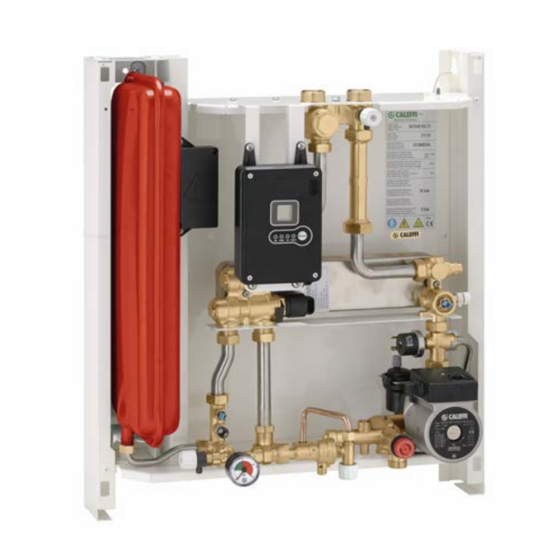
Dimensions
282,5
10
149
65
50.5 50.5
3/4" M
Installation
The SATK series HIU is designed for installation in a protected
domestic (or similar) environment and must not therefore be
installed or used outdoors, i.e. in areas directly exposed to the
weather. Outdoor installation may cause malfunctioning and
hazards.
If the device is enclosed inside or between cabinets, sufficient
space must be provided for routine maintenance procedures.
It is recommended that electrical devices are NOT placed
underneath the HIU, as they may be damaged in the event of safety
relief valve activation if not connected to a discharge tundish, or in
the event of leaks occurring at the hydraulic fittings.
If this advice is not heeded, the manufacturer cannot be held
responsible for any resulting damage.
In the event of a malfunction, fault or incorrect operation, the device
should be deactivated; contact a qualified technician for
assistance.
Preparation
After having established the point where the appliance is to be
installed perform the following operations:
· Mark the holes required for securing the HIU to the wall
· Mark the position of the hydraulic connections
Check the measurements again and begin laying the following
lines:
Hydraulic (see page 4):
1. connection to the central system line
2. heating circuit connection
3. connection to domestic hot water storage
4. domestic cold water circuit connection (for filling)
5. conveyance of safety relief valve and charging unit backflow
preventer discharge
Electric (see page 9):
1. 230 V (ac) – 50 Hz electric supply line
2. chrono-thermostat/thermostat line (potential-free)
3. hot water storage thermostat line (live line)
4. centralised bus line for heat meter data transmission (if required)
5. centralised electric supply line for heat meter (if required)
550
65
65
530
3/4'' F
S TK40103HE technical specifications
Medium:
Maximum percentage of glycol:
Maximum medium temperature:
Max. working pressure:
Nominal heat exchanger capacity:
Maximum recommended primary circuit flow rate:
Max. differential press. on modulating valve: Dp 150 kPa (1,5 bar)
Electric supply:
Maximum power consumption:
Protection class:
Pump:
Pump by-pass setting:
Actuators:
Probes:
Safety relief valve setting:
Safety thermostat:
Expansion vessel:
Pressure switch:
Materials
Components:
Fitting pipes:
Frame:
Protective shell cover:
Heat exchanger:
N.B.: the wall anchors (not supplied) can only guarantee effective
support if inserted correctly (in accordance with good technical
practice) into walls built using solid or semi-solid bricks. f working
with walls built using perforated bricks or blocks, mobile dividing
panels or any masonry walls other than those indicated, a
preliminary static test must be carried out on the support system.
Heat meter installation
The HIU is designed to fit a compact heat meter (with incorporated
return probe) with 1" threaded connections and 130 mm gauge.
Before carrying out any maintenance, repair or part replacement
work, proceed as follows:
- cut off the electric supply
- remove the cover
- close the shut-off valves
- empty the HIU using the drain cocks provided
Proceed as described below to install the heat meter:
- remove the template (A)
- remove the cap (B)
- install the flow meter on the return pipe
- install the flow probe in the M10 pocket (B).
Please refer to the heat meter technical data sheets for further
information.
B
3
- primary circuit:
1,6 MPa (16 bar)
- secondary circuit:
0,3 MPa (3 bar)
1,2 m
230 V (ac) ±10% 50 Hz
UPM3 15-70
45 kPa (0.45 bar)
stepper 24 V
NTC 10 k Ω
0,3 MPa (3 bar)
55°C ±3
- capacity
- pre-charge value:
0,1 MPa (1 bar)
- opening
40 kPa (0,4 bar)
- closing
80 kPa (0,8 bar)
brass EN12165 CW617N
RAL 9010 painted steel
brazed stainless steel
A
water
30%
85°C
15 kW
/h
3
80 W
IP 40
7 l
steel
PPE