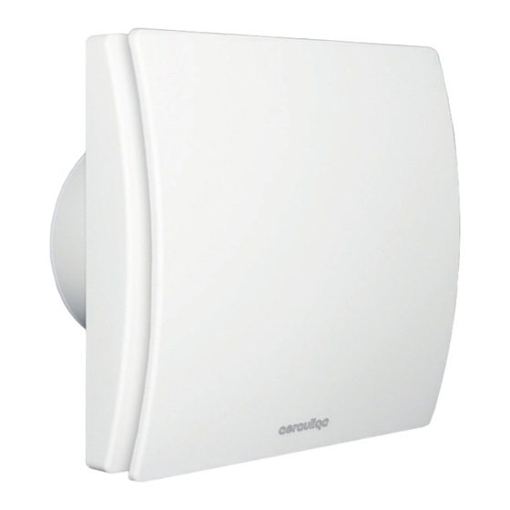
aerauliqa QDMEV Manual de instalação - Página 7
Procurar online ou descarregar pdf Manual de instalação para Ventilador aerauliqa QDMEV. aerauliqa QDMEV 16 páginas.

• Install the product so that the impeller is not accessible from the air outlet side as
verified by contact with the Test Finger (test probe "B" of the norm EN61032) in
compliance with the current safety regulations.
• Ceiling installation
In order to guarantee the IPX4 degree of protection against moisture in case of
ceiling installation, use the appropriate ceiling mount kit, which is not included. Use
only the rear entry hole for supply cables. If there is a possibility of condensation
along the air discharge duct, provide a drainage system to prevent condensation
from discharging into the environment through the fan.
Attention: do not mount the product on the ceiling without this kit.
introDuCtion
QDMEV is a decentralised mechanical ventilation unit designed to ensure air extraction in small/medium-
sized rooms. Suitable for air discharge in the presence of long ducted system. Wall, ceiling or window
installation (fig.1).
tECHniCal sPECiFiCations
• Material: high quality, impact and UV-resistant ABS colour RAL 9010.
• Design front cover removable for cleaning without the use of tools.
• High efficiency aerodynamic fan with "winglet" blades to optimise quietness and efficiency.
• Single phase EC Brushless motor for energy saving, with integral thermal protection.
• Motor mounted on high quality ball bearings.
• Selectable minimum speed for continuous running and intermediate speed.
• Option to boost from minimun speed through LS connection.
• Selection of the installation type (through wall or in-room).
• Selection of smart humidity control and intelligent run-on timer.
• Selection of constant volume mode.
• Suitable for continuous running.
• The fan is double insulated: no earth connection is required.
• IPX4.
• Power supply 220-240V~ 50/60Hz
oPEration
Upon power-up, the unit runs at the minimum continuous speed.
If humidistat or timer is activated, the unit runs at the intermediate speed.
If the external switch is activated, the unit runs at the maximum speed.
After the external switch is off, the unit continues to run at the intermediate speed for a period of time, then
it returns to the selected minimum speed (or to the intermediate speed in case humidistat or run-on timer
operation is on).
on
B
0
on
A
0
1
2
3
The functionalities can be set/enabled through the Dip Switches A and B on
the electronic circuit (with disconnected from the main supply unit).
4
7
