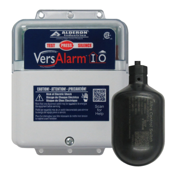
Alderon Industries VersAlarm I/O VLIO-0002 Manual de início rápido
Procurar online ou descarregar pdf Manual de início rápido para Sistema de segurança Alderon Industries VersAlarm I/O VLIO-0002. Alderon Industries VersAlarm I/O VLIO-0002 2 páginas. Indoor/outdoor alarm panel

VersAlarm
Indoor/Outdoor Alarm Panel | Model: VLIO-0002
QUICK START GUIDE
Step 2: Mount Enclosure
Determine the mounting location
for the VersAlarm™ I/O. Make
sure the power outlet or receptacle
is within five feet of the alarm panel
for the pre-installed power cable.
Hold the alarm up to the desired
mounting location, mark the drill
hole locations. Once marked, drill
pilot holes for screws (not included)
and use wall mount anchors
(not included) if necessary. Place
enclosure in mounting location,
adjust until the pilot holes are lined
up with the enclosure and fasten
screws to secure the alarm panel
in place.
Step 3: Power Cable and Float Switch
The alarm panel comes with a
pre-installed power cable and
alarm float switch. Refer to the
instructions for the alarm float
switch to determine the alarm
activation level and for proper
installation. If using the auxiliary
contacts, see step 4 for wiring.
CAUTION: Do not connect power until
installation/wiring is complete.
Mount alarm float switch
at alarm activation level
I/O
™
Plug power cable into
120VAC receptacle
Safety Guidelines
Before proceeding with the installation or operation of this product,
read all instructions thoroughly, as well as complying with all federal,
state and local codes, regulations, and practices. This product must
be installed by qualified personnel familiar with all applicable local
electrical and mechanical codes. Refer to the National Electrical Code
(NFPA 70). Failure to properly install and test this product can result in
personal injury or equipment malfunction.
Step 1: Remove Bottom Cover
Remove the bottom enclosure cover screw, slide directly downward
(1A) and then pull directly away (1B).
1A
1B
Step 4: Wiring
The diagram below shows the six terminals on the terminal block that
consists of three pairs of connections.
1) The pre-installed float switch is connected to terminals 1 and 2.
2) Installing an auxiliary device to terminals 3 and 4 is optional.
3) The pre-installed incoming power cable is connected to terminals 5
and 6, line (L1) in terminal 5 and neutral (N) in terminal 6.
4) NEVER leave ground wire exposed inside the panel, use provided
Wago connector for wire termination.
SENSOR
1
2
3
Installing Wire into Wago Connector:
1) Lift tab(s) upward.
2) Insert wire(s) into slot.
3) Press tab(s) downward.
4) Make sure wire(s) are secured.
WARNING
AUX
POWER
4
5
6
TO OPEN
TO CLOSE
WAGO
WAGO
