Alderon Industries ProbeX Series Manual de operação, manutenção e instalação - Página 2
Procurar online ou descarregar pdf Manual de operação, manutenção e instalação para Interruptor Alderon Industries ProbeX Series. Alderon Industries ProbeX Series 4 páginas. Vertical pump switch

Description of Operation
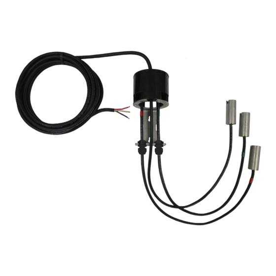
The ProbeX™ Pump Switch is a vertical pump switch operated by three suspension probes. Typically used for liquid
level control in storm water collection, pond fill, water tanks, sump pumps, pilot/control circuits to energize magnetic
motor contactors, and any similar application where the water levels need to be controlled. Available in 120/230VAC
bare lead (no plug), 120VAC piggyback plug, and 230VAC piggyback plug, 15 Amp models with standard or custom
power and suspension probe cable lengths. The power is transformed to a safe low voltage of 12VDC at the probes.
The ProbeX™ pump switch can be mounted to a pipe, wall, or flat surface with the include mounting bracket and
stainless steel pipe clamp (bolts/screws not included if mounting to a wall or flat surface). Three suspension probes
are included for reference, stop, and start levels in the mounting area. The stop (red) and start (green) probes are
pre-wired into cable grips on the mounting bracket which allows for easy adjustments of the off and on levels per
application. A RubberLox™ adjustable strap is included to secure excess probe cable below the pump switch housing.
Installation of the ProbeX™
1. Determine mounting method of the ProbeX™ for your application (WARNING! Review Safety Guidelines). For
mounting on a pipe or pump discharge pipe, see figure 1 and for wall mounting, see figure 2. For piggyback plug
models, make sure an outlet or receptacle is within the distance of the ProbeX™ power cable prior to mounting.
(Fig. 1 - Pipe Mount)
2. Determine the pumping range for your application. The reference probe is submerged in the water with the
distance between the stop and start probes creating the pumping range.
3. For "Pump Down" applications, see figure 4. The "Reference" probe is the lowest mounted probe, followed by
the "Stop" probe (red label) in the middle, and the "Start" probe (green label) on top. Loosen cable grips (Fig. 3) and
pull the cables through - raising or lowering to the desired levels and securely fasten by tightening the cable grips.
4. For "Pump Up" applications, see figure 5. The "Reference" probe is the lowest mounted probe, followed by the
"Start" probe in the middle, and the "Stop" probe on top. Loosen cable grips (Fig. 3) and pull the cables through -
raising or lowering to the desired levels and securely fasten by tightening the cable grips.
(Fig. 3)
Loosen / Tigthen to Adjust
Stop and Start Probe Sensor Levels
Page 2 | Installation Instructions
Alderon Industries • PO Box 827 Hawley, MN 56549 • P: 218-483-3034 • F: 218-483-3036 • alderonind.com
ProbeX
- Installation Instructions
™
(Fig. 4 - Pump Down)
(STOP)
(Fig. 2 - Wall Mount)
(2A)
(START)
Pumping
Range
(2B)
Mounting Bracket Holes
bracket only
bolts/screws not included
(Fig. 5 - Pump Up)
(STOP)
(START)
Pumping
Range
