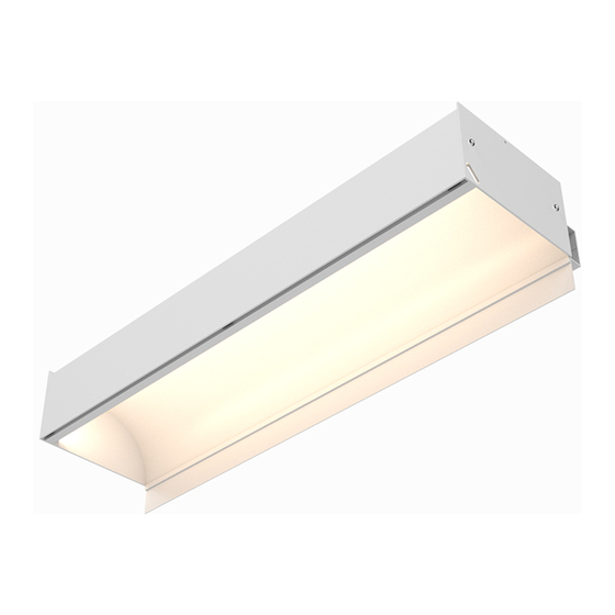
CALI alumLEDs ALS500T-RMW-HC Manual de instruções de instalação
Procurar online ou descarregar pdf Manual de instruções de instalação para Luz exterior CALI alumLEDs ALS500T-RMW-HC. CALI alumLEDs ALS500T-RMW-HC 16 páginas.
Também para CALI alumLEDs ALS500T-RMW-HC: Manual de instruções de instalação (16 páginas)

END VIEWS (With T-Bar Ceiling Trim)
7.0"
3.60"
Max.
3.27"
1.72"
1.38"
7.25"
Hanging Bracket Assembly
(ALS500T-RMW-HB)
FEATURES
APPLICATIONS
Indirect Lighting
LENS
Clear
LENGTH
Built to Order (± 0.25" Tolerance)
CONSTRUCTION
Aluminum Extrusion
FINISH
White Powder Coated
DRIVER
Remote
WEIGHT
4.50 lbs per foot
MOUNTING
Mounting Brackets or Aircraft Cable
Dry or Damp Location
UL1598, CSA C22.2#250.0
LISTING
UL8750, CSA250
UL2108, CSA C22.2 #9
Operating / Startup: -20° to 48°C (-4° to 120°F)
TEMPERATURE
RATINGS
Storage: -40° to 76°C (-40° to 170°F)
PRODUCT INFORMATION
• Indirect lighting
• 24 Volts DC for easy and safe installation
• Long life, energy efficient LEDs
• Available in 4 Watts up to 12 Watts Per Foot
• Can be ordered to specific lengths for when exact dimensions are known
Example: 10 x 10'6" (product is shipped in 8' max luminaires)
• Available for indoor (DRY) and (DAMP) rated installations
CONTENTS
DESIGN GUIDELINES
HANGING BRACKET MOUNTING
AIRCRAFT CABLE MOUNTING
REFLECTIVE FILM
TROUBLESHOOTING
CARE & MAINTENANCE
CALIFORNIA ACCENT LIGHTING, INC.
2820 E. Gretta Lane, Anaheim, CA 92806
ph. 800.921.CALI (2254) | fx. 714.535.7902 | [email protected] | calilighting.com
© CALI. All rights reserved. CALI reserves the right to make changes or withdraw specifications without prior notice.
X (Specified Length)
5.27"
1.72"
1.38"
7.25"
Aircraft Cable Assembly
(ALS500T-RMW-AC)
Page 2
Page 3 - 5
Page 6 - 9
Page 14
Page 15
Page 16
ALS500T-RMW-TB
READ ENTIRE GUIDE BEFORE STARTING INSTALLATION
IMPORTANT NOTICE:
VERIFY CORRECT LUMINAIRE WAS RECEIVED WITH
CORRECT COLOR TEMPERATURE, VOLTAGE, AND WATTAGE BEFORE CUTTING OR
INSTALLING. CALI WILL NOT BE RESPONSIBLE IF INCORRECT LUMINAIRE IS INSTALLED.
ELECTRICAL
• ALS500T-RMW requires a remote driver. The driver may be mounted on
top of the luminaire or in a remote location.
• Drivers are 120V - 277V (UNV) Input Voltage and 24VDC Output Voltage
• To calculate driver size, determine Watts per Foot.
Example: 4W per Foot
• Determine Length in Feet.
Example: 20'
• To calculate Load, Multiply Watts per Foot x Length in Feet
Example: 4W x 20'= 80W. The Load of the driver is 80 Watts.
• Maximum load for a Class 2 low voltage luminaire is 96 Watts
INSTALLATION RECOMMENDATIONS
• ALS500T-RMW can be mounted to concrete, wood, or metal using proper
mounting hardware.
• Ensure surface material can support the weight of the luminaire.
INSTALLATION TOOL REQUIRED
• Electric Hammer Drills (optional)
• 14.4 to 28 Volt Cordless Drills
• Phillips Bits - Sufficient Quantity
• Utility Knife
• Electrical Cords
• Marker
• Wire Strippers
INSTALLATION INSTRUCTIONS
Overview
• Long Nose Pliers
• Drill Bits - Concrete or Wood
• Electrical Three Ways
• Safety Glasses
• Measuring Tapes
• Chalk Line
1 / 29 / 2021 / Rev 2
Page 1 of 16
