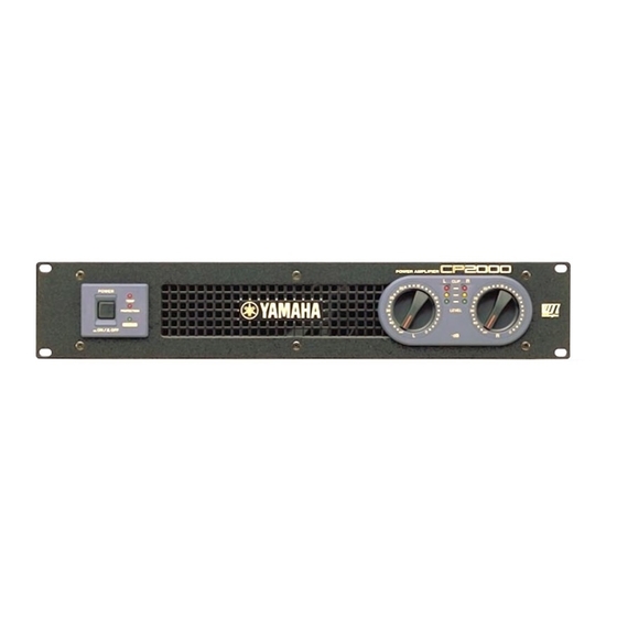
Yamaha CP2000 Manual de serviço - Página 18
Procurar online ou descarregar pdf Manual de serviço para Amplificador Yamaha CP2000. Yamaha CP2000 33 páginas. Yamaha power amplifier owner's manual
Também para Yamaha CP2000: Manual do Proprietário (20 páginas), Manual de serviço (33 páginas)

CP2000
1.2.10 Stability
The following conditions shall be met when a 10 kHz, -10dBu rectangular pulse is input and a capacitance of 10 pf ~ 0.47 µF is
connected in parallel with a load resistance of 4 Ω.
Overshoot Vp/Vo
Ringing: Within 5 waves
Next, when there is only a pure capacitance of 10 pf ~ 0.47 µF the following conditions shall be met.
< =
Vp/Vo
2.5
Ringing: There shall be convergence within 7 waves and no oscillation, etc.
1.2.11 Protection circuit
The protection circuit shall operate and the relay shall not open when a 10 Hz, +5.4 dBu sine wave is input and the output wave is
made to clip. Next, the protection circuit shall operate within two seconds and break the output when a 1 Hz, 0.0 dBu sine wave is
input. In addition, when the input signal is cut, it shall automatically recover within 10 seconds.
1.2.12 Efficiency
(1) The primary electrical power shall be measured and be within the range shown below when a 1 kHz, -6.6 dBu sine wave is input
to the input terminal.
330 W ± 50 W (U: 4.0 A ± 0.6 A,
(2) The primary electrical power shall be measured and be within the range shown below when the input terminal is grounded by the
introduction of the input terminal.
25 W ± 10 W
1.2.13 PC limiter and comp
Input a 1 kHz, -1.5 dBu sine wave to the input terminal and connect 1 Ω (± 5 %) as a load to the output terminal. Under these conditions,
< =
< =
a 10 V
Vrms
16 V sine wave shall be attained at the output. The total harmonic distortion ratio shall be THD=5 % or less.
Also at this time, the clip indicator shall come on. This inspection shall be completed within 30 seconds.
1.2.14 Signal indicator
The green signal indicator shall come on when a 1 kHz, -23 dBu sine wave is input.
In addition, the green and yellow signal indicators shall come on when a 1 kHz, -4 dBu sine wave is input.
2.
Bridge mode
2.1
Preparations
Input attenuator
Input terminal
Mode SW
Yamaha speaker processing
Output terminal
Load resistance
Measurement connection
2.2
Inspection
2.2.1 Gain
An output voltage of +24.0 ± 1.0 dBu shall be attained when a 1 kHz, -10 dBu sine wave is input to the input terminal.
18
All manuals and user guides at all-guides.com
< =
1.8
H: 2.0 A ± 0.3A)
(U: 0.33 A ± 0.13 A, H: 0.20 A ± 0.08 A)
L channel only operates. Set to MAX.
L channel cannon connector (No. 2 hot, No. 1, 3 ground)
Bridge
Off
Use L channel +, R channel +.
4 Ω + 4Ω, Non inductance resistor, input capacitance 500 W or more.
Set to a floating ground and connect at center point of load resistance.
SPEAKERS
MEASURING
INSTRUMENT
INPUT
GND
