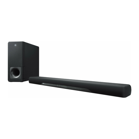
Yamaha ATS-CU2070 Manual de serviço - Página 18
Procurar online ou descarregar pdf Manual de serviço para Sistema de altifalantes Yamaha ATS-CU2070. Yamaha ATS-CU2070 50 páginas. Front surround system
Também para Yamaha ATS-CU2070: Manual do Proprietário (46 páginas)

YAS-CU207/ATS-CU2070/NS-WSW42
2.
How to Remove Parts Installed
to the Bottom Cabinet Assembly
2-1.
Removal of Driver Full-Range (Fig. 2)
*
The driver removal procedure is the same for
both right and left.
a.
Remove 4 screws ( ② ).
b.
Remove the solder of the connector and disconnect
the cable.
c.
Remove the driver full-range.
2-2.
Removal of Driver Tweeter (Fig. 2)
*
The driver removal procedure is the same for
both right and left.
a.
Remove 2 screws ( ③ ).
b.
Remove the solder of the connector and disconnect
the cable.
c.
Remove the solder of the connector and remove
the capacitor.
d.
Remove the driver tweeter.
Rubber sheet and the cloth
ゴムシー トと布
Driver full-range
スピーカーユニッ ト(フルレンジ)
②
スピーカーユニッ ト (ツィ ーター)
18
③
③
Driver tweeter
Capacitor
コンデンサー
2.
ボトムキャビネット Ass'y に
2-1. スピーカーユニット(フルレンジ)の外し方
※ スピーカーユニットの外し方は左右同じです。
a.
② のネジ 4 本を外します。
b.
コネクターの半田を取り除きケーブルを外します。
c.
スピーカーユニット(フルレンジ)を外します。
2-2. スピーカーユニット(ツィーター)の外し方
※ スピーカーユニットの外し方は左右同じです。
a.
③ のネジ 2 本を外します。
b.
コネクターの半田を取り除きケーブルを外します。
c.
コネクターの半田を取り除きコンデンサを外しま
す。
d.
スピーカーユニット(ツィーター)を外します。
②
Driver full-range
スピーカーユニッ ト(フルレンジ)
Fig. 2
取り付けてあるパーツの外し方
(Fig. 2)
(Fig. 2)
Bottom cabinet assembly
ボトムキャ ビネッ ト Ass'y
