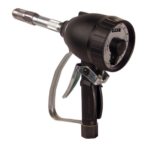
Alemite 3693-C Manual de serviço - Página 6
Procurar online ou descarregar pdf Manual de serviço para Unidade de controlo Alemite 3693-C. Alemite 3693-C 12 páginas. Preset metered control valve
Também para Alemite 3693-C: Manual de serviço (8 páginas)

Clean and inspect
1 Clean all metal parts in cleaning solvent.
Solvent should be environmentally safe.
2 Inspect all parts for wear and/or
damage. Replace as necessary.
3 Closely inspect mating surfaces of all
components for any imperfections.
Ensure smooth and clean contact is
obtained when assembled.
Assembly
NOTE
Refer to Fig. IPB 1, page 10 for
component identification.
NOTE
Prior to assembly, certain components
require lubrication (³ Table 2 for
details).
Components lubricated in clean oil
Item
Description
O-ring
Washer
O-ring
O-ring
Quad-ring
Metered control valve
Metering mechanism assembly
1 Install and seat washer (9) into head of
housing (8).
2 Install o-ring (10) into gland nut (11).
3 Screw gland nut (11) into housing (8).
4 Tighten gland nut (11) securely.
5 Position chamber and pinion
assembly (5) gear end upward.
6 Install planetary gear (6) into chamber
and pinion assembly (5).
7 Position spindle and gear assembly (7)
onto chamber and pinion assembly (5).
8 With spindle and gear assembly (7)
pointed upward, install entire
subassembly into housing (8).
9 Install o-ring (4) onto cap (3).
NOTE
Use care passing o-ring (10).
NOTE
Rotate spindle and gear assembly (7) so
flat of shaft points between posts of
register assembly. This aids in
installation of worm gear (13).
Table 2
NOTE
Do not allow subassembly to shift
during installation or once installed.
Failure to comply may result in
damage to equipment.
10 Install hand guard (32) onto housing (8).
11 Screw cap (3) into housing (8) and
tighten cap (3) to ft.lbf. (47 Nm).
Register assembly
12 Install register assembly (20) onto
housing (8). Make sure register seats on
four pins.
13 Install screws (21) that secure register
assembly to housing (8) and tighten
securely.
14 Apply threadlocker to setscrew (12) and
install into worm gear (13).
15 Install worm gear (13) with spur gear
upward onto shaft of spindle and gear
assembly (7).
NOTE
Make sure worm gear (13) setscrew
points toward flat on spindle and gear
assembly (7). Verify gear meshes
properly with register gear.
16 Install washer (22) onto bottom post of
17 Install pointer gear (23) with flat surface
NOTE
Make sure gears mesh evenly.
18 Move worm gear (13) straight up or
19 Tighten setscrew securely.
Lock pawl
20 Install and seat spring (16) with flat
21 Install lock pawl (14) onto housing post.
NOTE
Make sure lock pawl (14) properly
engages spring (16).
22 Install retaining ring (15) that secures
register assembly.
downward onto washer.
down so gear wheel meshes evenly with
pointer gear.
portion first onto post on housing (8)
with spring (16) seating in notch.
lock pawl (14) to post.
