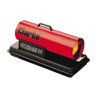
Clarke 6920268 Instruções de funcionamento e manutenção - Página 10
Procurar online ou descarregar pdf Instruções de funcionamento e manutenção para Aquecedor Clarke 6920268. Clarke 6920268 20 páginas. Paraffin/diesel heaters

Bi-Monthly
Fan.
Having removed the top cover, thoroughly clean the fan using a cloth moistened
with paraffin or light solvent, and dry using an air line if possible.
Output Air Filter.
Remove the grille, and pull off the Intake Air Filter, revealing the 3 screws securing
the filter housing. Remove the screws and pull off the housing to reveal the Output
Air Filter. If contaminated, this filter must be renewed.
In dusty environments this procedure should be carried out, monthly
Nozzle.
Having removed the top cover, gently unscrew and remove the burner head,
and unscrew the nozzle. Clean, using compressed air and a soft brush, if
necessary. DO NOT prod or poke the nozzle in any way, with a metal tool.
Following a period of Storage.
Pump Pressure.
Before putting the heater back into service, following a period of storage, you
should carry out all checks previously specified. In addition, you should test and
adjust if necessary, the Air Pump Pressure, as follows:
Near the centre of the Grille, is a cut-out to accommodate the Air Pump Pressure
Relief Valve, and a plug for installing a Pressure Gauge as shown in fig. 5.
Remove the plug, and install a gauge with a resolution of at least 0.02 bar (0.3psi).
Start the heater, and observe the pressure reading, which should be as follows:
Model
XR55
0.28 - 0.30bar (4.06 - 4.35psi)
XR75
0.26 - 0.33bar (3.84 - 4.8psi)
XR105
0.30 - 0.36bar (4.45 - 5.3psi)
XR155
0.30 - 0.39bar (4.45 - 5.7psi)
To adjust the pressure, insert an Allen key into the hex socket in the end of the Relief
Valve Adjuster, and undo the Adjuster Nut. Turn the Allen key clockwise to increase
pressure, and anticlockwise to decrease. Tighten the securing nut when the
correct pressure is reached, ensuring the Allen key does not turn in the process.
Air Pump Pressure
Fig. 5
10
