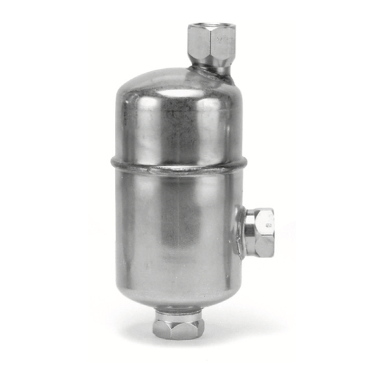
Armstrong 11AV Manual de instalação e operação - Página 3
Procurar online ou descarregar pdf Manual de instalação e operação para Bomba de água Armstrong 11AV. Armstrong 11AV 6 páginas. Free floating lever air/gas vents

Installation Procedures
Install air vents at all the high points on liquid service systems, hydronic systems, or any liquid storage or distribution
system. See Figures 1, 2 & 3 for typical installations.
Do not exceed the maximum allowable pressure noted on the label on the side of the air vent
1
body. Also, check to see if the air/gas vent has the proper maximum differential pressure for your
particular application.
Be certain the vent is installed properly. Note the direction of flow arrow on the label and the red
2
label indicating UP for air and gas venting service.
Before installing the vent, flush out the line to remove loose dirt. Use pipe dope or teflon tape
3
sparingly and on male threads only. Leave the end thread exposed to avoid introducing sealant into the
system.
When tightening a pipe into either the inlet or outlet fittings of an 11AV, 22AV or 13AV use only the
4
hex-shaped fittings as wrenching surfaces. Do not use other parts of the vent for wrenching as
unnecessary stress may be placed on the vent body.
The inlet and outlet piping should be the same size as the air vent connections. Do not reduce the size
5
of the inlet on light loads; however, smaller pipe or tubing may be used on the outlet. Keep the piping
as short as possible, with a minimum of valves and fittings. If you are installing an air vent without
an equalizing connection, do not use elbows in the inlet line from the equipment to the vent.
Install gate valves or full ported ball valves (Do Not Use Globe Valves) so the air vent can be isolated
6
from the system to permit servicing. If the air vent is installed in a closed piping arrangement, install a
union on each side of the air vent.
7
Do Not use a pipeline strainer in the line leading to the vent.
Air vents should be installed so that they can be checked periodically. A drain line should be piped to
8
a floor drain or to a visible location where it can be regularly checked for leakage.
Caution: Do not install air vents with an open discharge where a malfunction could cause damage
i.e. above false ceilings.
11AV Air Vent
To Drain
Ball Valve
Return
High Point on Main
Figure l. Installation of Model
11AV automatic air vent on high
point of main.
22AV Air Vent
To Drain
Flow
Figure 2. Installation of a Model 22AV
automatic air vent on loop in piping.
3
13AV Air Vent
A
B
Figure 3. Continuous venting using
a Model 13AV with an equalizing
line where large amounts of air
must be vented. As air enters line
A, water leaves through line B.
