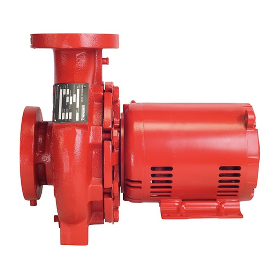
Armstrong 4280 Series Instruções de instalação e de utilização - Página 3
Procurar online ou descarregar pdf Instruções de instalação e de utilização para Bomba de água Armstrong 4280 Series. Armstrong 4280 Series 4 páginas. Motor mounted pump
Também para Armstrong 4280 Series: Instruções de trabalho de serviço (4 páginas), Manual de instruções de instalação e funcionamento (12 páginas), Manual de instruções de instalação e funcionamento (10 páginas)

If the unit is to be mounted on fabricated steel work or similar
structure, the unit should be set over, or as near as possible to,
the supporting beams or walls and to be so supported that the
unit is not distorted by any yielding or springing of the structure .
With the proper gauge, check the suction and discharge flanges
of the pump for vertical position.
Slight misalignment from vertical at this point may be corrected
by inserting shims under the motor feet.
When the unit is completely level, the foundation bolts should
be tightened evenly and firmly.
4 pump piping - general
Never connect a pump to piping, always start piping from pump.
Use as few bends as possible and preferably long radius elbows.
Install good supports under suction and discharge piping with
anchors near but independent of the pump.
Make sure piping exerts no strain on pump as this would distort
the casing and cause pump misalignment.
Suction and discharge pipes may be increased at pump nozzle
to suit pump capacity and particular conditions of installation.
Use eccentric reducers on suction connection.
Layout the suction line with a continual rise towards the pump
without high points, thus eliminating possibility of air pockets
that may prevent the pump from operating.
A strainer of three or four times the area of the suction pipe,
installed in the suction line, will prevent the entrance of foreign
materials into the pump. V" (3mm) diameter perforations in
the strainer are typical.
For aquatic applications: Strainer openings must not exceed
0.05 in
(0.3cm
) /¼" (6mm) dia hole and the open area be no
2
2
less than 10 in
(65cm
) and be 4:1 or greater ratio to the cross-
2
2
sectional area of the strainer inlet connection. The strainer
basket shall have a minimum internal volume determined by the
inlet connection size, such as:
1.5" (40mm) or less: 25 in
3
2" (50mm) or greater: 90 in
Test suction line for air leaks before starting; this becomes es-
sential with long suction line or static lift.
Install, at pump suction, a straight pipe of a length equivalent to
4 or 6 times its diameter; this becomes essential when handling
liquids above 1200°f (500°c). Armstrong suction guides may be
used in place of the straight pipe run and in-line strainer.
(410 cm
)
3
(1475 cm
)
3
3
Series 4280 Motor
Mounted Pump
Install isolation valve in both suction and discharge lines on
flooded suction application; this is used mainly to isolate the
pump for inspection or repair.
Install a non-slam check valve in discharge line between pump
and isolation valve to protect pump from excessive back pres-
sure and to prevent water running back through the pump in
case of driver failure. Armstrong FIo-Trex valve may be used in
place of check valve and isolation valve on pump discharge.
caution
Discharge valve only must be used to reduce the
pump flow, not the suction valve.
Care must be taken in the suction line layout and
installation, as it is usually the major source of
concern in centrifugal pump applications.
oper ation - series 4280 motor
mounted pump
1 starting pump
The pump must be fully primed on start up. Fill the pump cas-
ing with liquid and rotate the shaft by hand to remove any air
trapped in the impeller. Air will not be trapped in the casing
providing the self-venting center-line discharge is on top, in the
vertical position.
Bump or energize the motor for a fraction of a second and check
that the rotation corresponds with the directional arrow on the
pump casing.
To reverse rotation of a three phase motor, interchange any two
power leads.
Start the pump with the discharge valve closed and the suction
valve open, then gradually open the discharge valve when
the motor achieves full operating speed. The discharge valve
may be cracked or open slightly at start up to help eliminate
trapped air.
When stopping the pump: Close the discharge valve and
de-energize the motor.
2 general care
note: Check rotation arrow prior to operating the unit.
Series 4280 rotation is clockwise when viewing from
the drive end, looking from behind the motor.
i n s ta l l at i o n &
o p e r at i n g i n s t r u c t i o n s
3
