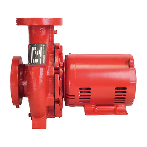
Armstrong 4280 Series Instruções de trabalho de serviço - Página 2
Procurar online ou descarregar pdf Instruções de trabalho de serviço para Bomba de água Armstrong 4280 Series. Armstrong 4280 Series 4 páginas. Motor mounted pump
Também para Armstrong 4280 Series: Instruções de instalação e de utilização (4 páginas), Manual de instruções de instalação e funcionamento (12 páginas), Manual de instruções de instalação e funcionamento (10 páginas)

s e rv i c e wo r k
Series 4280 Motor
i n s t r u c t i o n s
Mounted Pump
2
3
1
4
4
Servicing Armstrong Series 4280 pumps
Refer, also, to Armstrong Installation & Operating Instructions
for series 4 28 0 motor mounted pumps: File No: 42.80
All component numbers shown in this document refer to the
sectional view on front cover
The Series 4 28 0 pump is a motor mounted or close-coupled
type pump, mounted on a ball bearing motor. The pump should
be secured to the foundation by means of capscrews inserted,
through the motor feet, into flush type anchors embedded in
the foundation. This is necessary in order to enable the motor
assembly, with pump adapter and impeller to be pulled back-
wards out of the pump casing. when servicing the unit.
breakdown procedures:
1. electrical wiring
caution
Exercise extreme care when handling power wiring.
Ensure that the fuses are removed or breaker discon-
nected in the power line to the motor. Disconnected
power should be within sight of the pump being ser-
viced and tagged with the reason for disconnection.
6
101
6
7
4
103
104
If the pump and/or motor assembly is to be serviced on a
bench, the motor wiring must be disconnected. This may not
be necessary if the pump is to be serviced in place on the
foundation.
100
2 . isolation valves
If the system is not drained: Ensure that the suction and dis-
7
charge piping isolation valves are closed. Remove drain plug
8
[ 105] from the bottom of the casing and drain the pump.
3 . mounting capscrews
8
The motor mounting capscrews must be removed from the
8
foundation to permit removal of the rotating assembly out of
the pump casing [ 10 0].
4 . prepare assembly for removal
105
Remove the casing capscrews and washers [ 104 & 103].
Pry bars may then be inserted between the casing [ 10 0] and
adapter [40]. Care should be taken not to apply pressure to the
outside diameter of the adapter, to prevent possible breakage.
Outside pressure should be on the casing only.
5 . remove rotating assembly
The rotating assembly (motor, adapter and impeller [ 10, 40 &
8 0]) may now be pulled back out of the casing.
Prior to removing the rotating assembly ensure that the casing
is supported properly. If flexible connectors are installed in the
piping, support the casing in such a manner as to prevent the
casing weight from hanging on the flexible connectors.
6. rotating assembly notes
The impeller [8 0] is fastened directly to the motor shaft and
must be removed in order to replace the mechanical seal
[6 0/62]. This may be accomplished while the pump is still on
the foundation or more conveniently, on a work bench.
7. impeller capscrew
The impeller [8 0] should be prevented from rotating while
the capscrew [86] is loosened. A heavy screwdriver may be
inserted between the impeller blades to enable the impeller
capscrew to be backed off with a socket wrench. Remove the
impeller capscrew and washer [86 & 83]
8. pump impeller
Using wheel pullers, with the jaws behind the rear shroud of the
impeller [8 0] (Behind a vane at each side) pull the impeller free
of the pump shaft. Impellers that are difficult to remove may
be loosened by heating the impeller hub with a torch during
the pulling process. Remove the impeller from the motor shaft.
