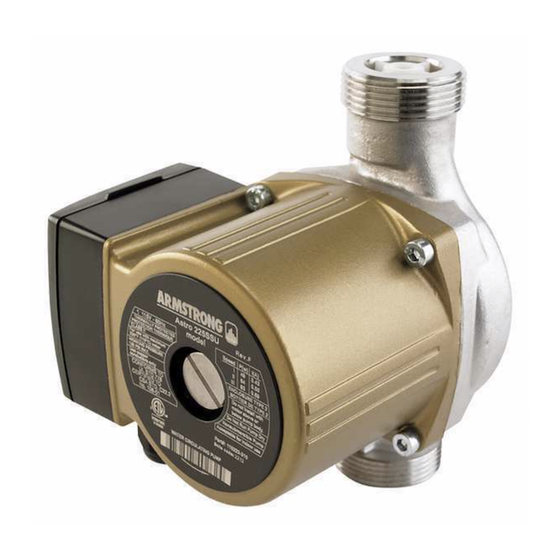
Armstrong ASTRO 250CI Manual de instruções de instalação e funcionamento - Página 6
Procurar online ou descarregar pdf Manual de instruções de instalação e funcionamento para Bomba de água Armstrong ASTRO 250CI. Armstrong ASTRO 250CI 8 páginas. 2, 3-speed circulators

i n sta l l at i on &
op era t i ng i n str u ct i on s
6
Speed setting of Astro 2 3-speed circulators:
The speed of these pumps can be adjusted with a 3-speed
rotary switch. On speed setting 1, the pump operates at
approximately half the performance of the speed setting 3
(maximum speed) and consumes about half the power of full
speed operation.
wa r n i n g
Never operate the circulator dry as permanent damage may
occur. Never shut off the discharge or restrict suction fl ow
while the circulator is operating.
The venting of the rotor chamber may be done automatically.
However, to assure proper and faster venting of this circulator,
we recommend the manual venting procedure as follows:
5 .0 installation troubleshooting guide
fault
possible cause
Noise from radiator
Excessive pressure passing the thermostatic
valve.
The radiator is not giv-
The thermostatic valve is jammed or blocked.
ing off any heat
The heating system is not balanced.
Pump generates little
Incorrect discharge direction.
or no output
Dirty impeller
Suction port blocked
Outlet blocked
Isolation valve closed
Dirty strainer
Air in the pump
Pump at lowest/medium speed level
Pump set point is too low
Astro 2, 3-speed
circulator models
1 Place a container under the back of the circulator to catch
any water that may run out.
2 Be sure power to the circulator is off at the fuse or
circuit breaker.
3 Loosen plug on the back of the motor but do not remove.
4 Continue until water appears.
5 After a suffi cient amount of water free of air bubbles has
passed, retighten the plug.
6 The circulator can now be started.
liquid temperature
167 °f ( 75°c)
194°f (9 0°c)
230°f ( 110°c)
remedy
• Reduce the speed setting. Flow decreases will
reduce system pressure and eliminate the noise.
• Shut off all other radiators in the system, and
set the pump at maximum speed.
• Once the blockage has been dislodged
reopen the radiators and adjust pump to origi-
nal speed setting.
• Re-assess the system. Fit new commissioning
valves on all radiators (may be integrated in the
thermostatic valves) to enable an even distribu-
tion of the fl ow.
• Turn pump 180°
• Open pump and clean impeller
note: Close isolation valves if present
• Open pump and clean housing
note: Close isolation valves if present
• Clean isolation valves
• Open isolation valves
• Clean strainer
• Switch off pump and open bleed screw to vent.
• Set pump to the next higher speed level.
• Increase set point on the pump or controller.
minimum inlet pressure
1.6 f t (0.5 m)
9 . 2 f t (2. 8 m)
36.1 f t ( 11.0 m)
