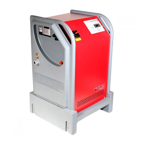
Armstrong 3750 Manual de instruções de instalação e funcionamento - Página 6
Procurar online ou descarregar pdf Manual de instruções de instalação e funcionamento para Controlador Armstrong 3750. Armstrong 3750 14 páginas. Pulpress pressurisation unit

i nsta ll at ion &
operat in g in str uct ion s
6
8.0 typical mthw sealed system –
max. 120°c
The arrangement of the mthw scheme is similar to the lthw
system above but has, in addition, an intermediate vessel
installed between the expansion vessels and the system
connection. The volume of water contained in this vessel
ensures that the return temperatures at the boiler are not
transferred to the expansion vessel, where damage to the
diaphragm would otherwise occur.
warning notes:
1 Packed-gland circulating pumps must not be used in
sealed systems.
2 Water treatment must not be added to the system via the
3750 Pulpress break tank.
3 No part of the set, expansion vessel, intermediate vessel
or connecting pipe is to be lagged.
4 Precautions should be taken to ensure that Lock Shield
Valves are protected against unauthorised closure.
9.0 stor age
Store in a dry place. Protect against dirt, damage and frost.
10.0 limitations
1 Maximum system working pressure: 10 bar.
2 Maximum flow temperature 120°c.
3 Electrical supplies: 1 phase, 50 or 60 Hz, 220 or 240 volts.
4 Power supply fluctuation: +/- 10% maximum.
5 Humidity non-condensing: 80% rh up to 31°c
decreasing linearly to 50% rh at 40°c.
6 Ambient temperature: -5°c to 40°c.
7 Water supply pressure 0.8 bar minimum to 6.8 bar
maximum with ballcock fully open.
8 System fill pressure:
8.1 Low pressure pump(s) – 0.5 to 2.5 bar.
8.2 Medium pressure pump(s) – 1.5 to 5.5 bar.
9 Maximum water temperature for expansion vessels:
9.1 Continuous – 70°c above this intermediate vessels
must be used.
9.2 Intermittent – 100°c.
10 Maximum total boiler rating – refer to graph pu3750.
11.0 protection
The set must be protected from the formation of condensa-
tion. If there is a likelihood of condensation forming on or in
the control panel then an anti-condensation heater should be
fitted. Contact our service department for details.
3750 Pulpress
pressurisation unit
12.0 gener al notes
1 The sets comprise one or two pumps operating on a duty/
stand-by arrangement.
2 Each set is sized to bs7074 and custom built for a specific
application, any change in the system conditions shown
may necessitate a change in the design or settings.
3 System must be completely flushed out, to remove any
metal particles, dirt etc, which may damage the set.
4 The system should be pressure tested, to eliminate leaks.
5 Under no circumstances must any attempt be made
to introduce water treatment to the system via the
break-tank.
6 No part of the set, connecting pipe or expansion vessel(s)
are to be lagged.
7 Fill the system via the quick-fill connection. Do not use the
set to fill the system.
13 .0 installation
13 .1 mechanical
1 Install the set on a flat and even surface.
2 Site set with sufficient space to the front, left and right
sides of the unit for maintenance purposes.
3 Connect the cold water mains supply, via a stopcock, to
the ballcock in the break tank. (Water supply pressure 0.8
bar minimum with ballcock fully open).
4 Arrange break tank overflow pipe to discharge into a
convenient drain in line with clause 30 of the Water supply
Bye-laws 1989 edition.
5 Make a connection from the set to the return side of the
boiler and suction side of the circulating pump(s). If
intermediate vessels are provided these should be fitted
in this connection with the set and expansion vessels
connected to the bottom of the vessel and the system to
the top of the vessel. A manual air vent should be fitted in
the pipe work close to the top of the vessel, see general
arrangement drawing provided. Ensure pump(s) are
vented by loosening the vent cap on top of the delivery
branch of the pump. Care must be taken not to over
tighten the system or water inlet connections.
6 Never dry run the pump.
7 For wall mounting, wall structure will need to be
determined to select appropriate fasteners. Ensure there
are no pipes or electrical cables running behind where the
wall bracket is to be secured.
13.2 electrical
1 The power supply required is 240 volt +/-10%, 1 phase,
50 Hz or 60 Hz to suit motors fitted.
2 The incoming supply should be connected to the door
interlocked isolator from a local 10 amp switched fused
spur and if possible an elcb unit.
