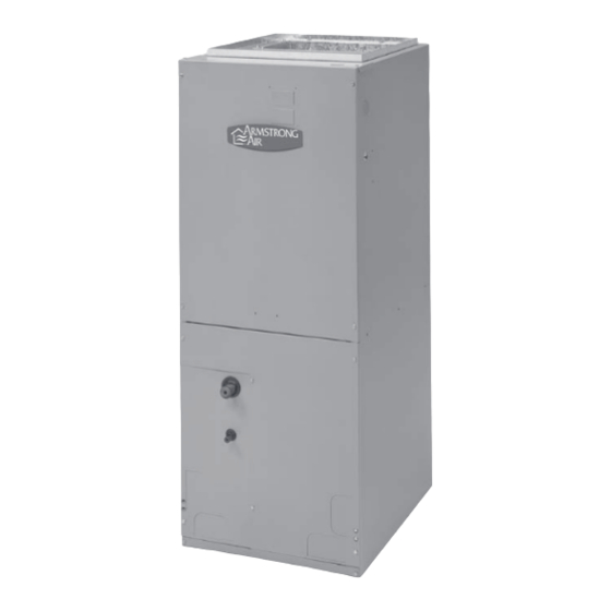
Armstrong Air BCS2 Series Manual de instruções de instalação - Página 13
Procurar online ou descarregar pdf Manual de instruções de instalação para Manipuladores de ar Armstrong Air BCS2 Series. Armstrong Air BCS2 Series 15 páginas.

Blower Performance Chart
Air
Handler
Model
Blower Speed
Low* (Red)
18
Med (Blue)
High (Black)
Low (Red)
24
Med* (Blue)
High (Black)
Low (Red)
30
Med* (Blue)
High (Black)
Low* (Red)
36
Med (Blue)
High (Black)
Low (Red)
42
Med* (Blue)
High (Black)
Low (Red)
48
Med* (Blue)
High (Black)
Low (Red)
60
Med* (Blue)
High (Black)
All data given while air handler is operating with a wet DX coil and air filter installed.
Speeds marked in bold with an asterisk* are the factory settings for both heating and cooling.
Cooling speeds should not be reduced below factory settings.
Different speeds can be set for heating mode.
Cooling (cooling only or heat pump)
When the thermostat calls for cooling, the circuit between R and
G is completed, and the blower relay is energized. The Normally
Open contacts close, causing the indoor blower motor to operate.
The circuit between R and Y is also completed; this circuit closes
the contactor in the outdoor fan motor. Circuit R and O energizes
the reversing valve, switching it to the cooling position. (The
reversing valve remains energized as long as selector switch is
on the COOL position.)
Heating (electric heat only)
When the thermostat calls for heat, the circuit between R and W
is completed, and the heater sequencer is energized. A time
delay follows before the heating elements and the indoor blower
motor comes on. Units with a second heat sequencer can be
connected with the first sequencer to W on the thermostat
subbase or connected to a second stage on the subbase.
Heating (heat pump)
When the thermostat calls for heat, the circuits between R and Y
and R and G are completed. Circuit R-Y energizes the contactor
13
CFM @ESP. -in. W.C.
0.10
0.20
722
702
994
926
1036
958
722
702
994
926
1036
958
929
916
1059
1043
1290
1271
1135
1120
1354
1345
1494
1469
1202
1192
1404
1413
1540
1530
1593
1582
1759
1709
1886
1820
1782
1755
2066
1960
2109
2067
SEQUENCE OF OPERATION
0.30
0.40
656
609
838
707
873
779
656
609
838
707
873
779
890
842
1014
948
1213
1153
1112
1079
1317
1260
1417
1336
1160
1116
1386
1303
1507
1386
1526
1444
1636
1538
1742
1606
1672
1554
1860
1714
1949
1770
starting the outdoor fan motor and the compressor. Circuit R and
G energizes the blower relay starting the indoor blower motor.
If the room temperature should continue to fall, the circuit
between R and W1 is completed by the second stage heat room
thermostat. Circuit R-W1 energizes a heat sequencer. The
completed circuit will energize supplemental electric heat (if
applicable). Units with a second heater sequencer can be
connected with the first sequencer to W1 on the thermostat or
connected to a second heating stage W2 on the thermostat
subbase.
Emergency Heat (heating heat pump)
If selector switch on thermostat is set to the emergency heat
position, the heat pump will be locked out of the heating circuit,
and all heating will be electric heat (if applicable). A jumper
should be placed between W2 and E on the thermostat subbase
so that the electric heat control will transfer to the first stage heat
on the thermostat. This will allow the indoor blower to cycle on
and off with the electric heat when the fan switch is in the AUTO
position.
0.50
517
626
663
517
626
663
737
842
1043
995
1090
1250
998
1192
1254
1318
1395
1446
1393
1476
1586
