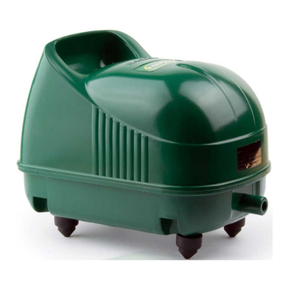
Blagdon Koi Air 65 Folheto de instruções - Página 10
Procurar online ou descarregar pdf Folheto de instruções para Equipamento para relva e jardim Blagdon Koi Air 65. Blagdon Koi Air 65 16 páginas. Air pump
Também para Blagdon Koi Air 65: Manual de instruções (9 páginas)

Changing Replaceable Parts
Koi Air pumps have been designed to run reliably for many years if correctly maintained. Koi
Air pumps, in common with all air pumps, contain perishable rubber parts that have a
limited life span. These parts have been designed so they can be easily replaced therefore
maintaining the excellent pumping performance.
IMPORTANT: As a rule all perishable rubber parts should be replaced annually.
!
This will ensure that the Koi Air is giving the optimum pumping performance.
Tools Needed
Medium sized Phillips head screwdriver.
A pair of Pliers.
Replacing the Air Intake Foams
Step by step guide
1. Remove the screw from the air filter cover part 1.
2. Remove and replace the air filter seal and air
filter foam parts 2/3.
Repeat steps 1 and 2 in reverse order to reassemble.
If you wish to change the flapper valves, move to changing
the flapper valves section 9.
!
IMPORTANT: Before commencing any maintenance on your Koi Air pump,
ensure it is isolated from the mains electricity supply.
Replacing the Outlet Foams
Step by step guide for Koi Air 25
1. Remove the air filter cover part 1.
2. Remove the 4 screws from the air pump base part 7 and remove the lid. Check that the
cover lid seal part 5 remains in place.
3. Remove the six screws from the motor base plate part 23 and gently lift the whole motor
from the air pump base part 7.
4. The three outlet foams part 32 and the outlet seal 6 can now be removed and replaced.
Repeat steps 1 and 4 in reverse order to reassemble.
Replacing the Outlet Foams
Step by step guide for Koi Air 50 / 65
1. Remove the air filter cover part 1.
2. Remove the 4 screws from the air pump base part 7 and remove the lid. Check that the
cover lid seal part 5 remains in place.
3. Remove the six screws from the motor base plate part 25 and gently lift the whole motor
from the air pump base part 7.
4. The three foams part 34 and the outlet seal part 33 and 6 can now be removed and replaced.
Repeat steps 1 and 4 in reverse order to reassemble.
8. MAINTENANCE
(See Diagram)
(
See Diagram)
(
See Diagram)
3
4
8
7
Replacing the Intake Foams
1
2
