Distech Controls Allure ECL-600 Series Manual de instalação - Página 8
Procurar online ou descarregar pdf Manual de instalação para Acessórios Distech Controls Allure ECL-600 Series. Distech Controls Allure ECL-600 Series 17 páginas. Extension modules
Também para Distech Controls Allure ECL-600 Series: Manual de instalação (16 páginas)
Subnet-Wiring
The subnet is used to connect a range of Allure Series Communicating Sensors:
£
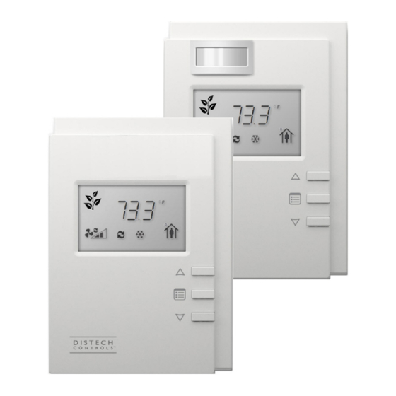
The Allure EC-Smart-Vue sensor is a communicating room temperature sensor with backlit display graphical menus and VAV balancing capabilities.
£
The Allure EC-Smart-Comfort and Allure EC-Smart-Air Communicating Sensors are a range of communicating room temperature sensors.
Connect the Allure Series Communicating Sensor to the controller's Subnet Port with a standard Category 5e Ethernet patch cable fitted with RJ-45 con-
nectors. Refer to the Network Guide for extensive information and requirements for the connection of the Allure Series Communicating Sensor. It con-
tains information about network topology and length, cable type, setting the Subnet ID, etc. It can be downloaded from www.distech-controls.com web-
site. See also the Hardware Installation Guide supplied with Allure Series Communicating Sensor.
If you make your own patch cable, see the Allure Series Communicating Sensor Hardware Installation Guide.
Protect the controller's connector from being pulled on when a cable to Allure Series Communicating Sensor is
connected. Create a strain-relief by looping the cable and attaching it to a solid object with a nylon tie so that a tug on
the cable will not pull out the connector on the controller.
Communications Wiring
ECx-400 UUKL IO Extension Modules are connected to the SUBNET– and SUBNET+ terminals of the ECB-600 UUKL controller. The Network Guide
provides extensive information and requirements to implement the subnetwork for the ECx-400 UUKL I/O Extension Modules. It contains information
about network length, cable type, controller addressing, etc. See the Hardware Installation Guide supplied with the ECx-400 UUKL I/O Extension Mod-
ule. It can also be downloaded from the www.distech-controls.com website. For the UUKL extension module, refer to the Distech Controls UUKL Smoke
Control System Design Guide.
For optimal performance, use Distech Controls 24 AWG (0.65 mm) stranded, twisted pair shielded cable or refer to the Network Guide for cable specifi-
cation. For the UUKL extension module, refer to the Distech Controls UUKL Smoke Control System Design Guide. The subnetwork communication wire
is polarity sensitive and the only acceptable topology is to daisy-chain the cable from one I/O Extension Module to the next.
As shown below:
£
The first and last daisy-chained subnetwork device must have its EOL resistors enabled / in-
stalled. All other devices must have their EOL resistor disabled (default factory setting).
£
When the subnetwork data bus is connected to a following device, twist data bus shields to-
gether.
£
Isolate all shields with electrical tape so there is no exposed metal that can touch ground or other
conductors.
£
The shield of the data bus must be connected to the electrical system ground at only one point –
usually at one end of the bus as shown below.
£
The I/O Extension Module and the Allure Series Communicating Sensor share the same subnet-
work.
ECB-600
ECL-600
8 / 16
ECx-4XX
ECx-4XX Sub-
Network Bus
Electrical
ECx-4XX Sub-Network Bus
System
Shields: Twist together and
Ground
Isolate with electrical tape
Figure 7:
Subnetwork bus shielding
ECx-4XX
Data Bus: Shielded
Twisted Pair Cable
ECx-4XX Sub-
Network Bus
Shield: Isolate
with electrical
tape