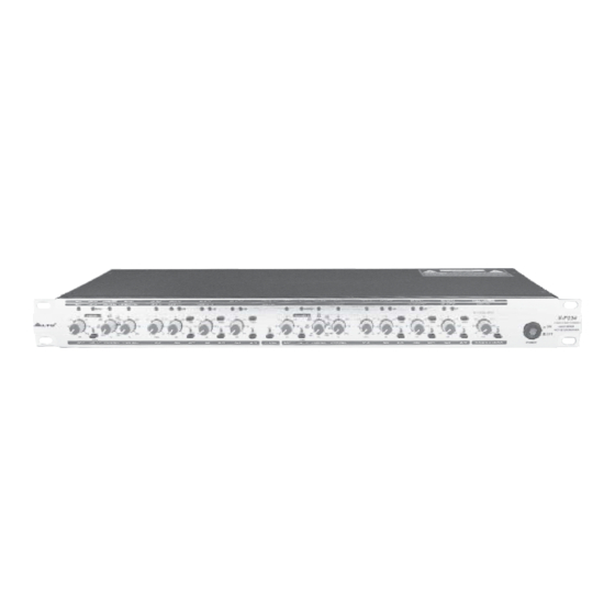
Alto X-P234 Manual do utilizador - Página 10
Procurar online ou descarregar pdf Manual do utilizador para Crossover Alto X-P234. Alto X-P234 18 páginas. 2-way/3-way stereo, 4-way mono active crossover
Também para Alto X-P234: Manual do utilizador (8 páginas)

14.Mute for High Output
This button mutes the high frequencies output.
15.CD Horn
Abbreviation for 'Constant Directivity Horn', this button can be used to boost the high frequencies, so that the
power loss of it during the long distance transmission can be compensated for.
30.Threshold Setting
To prevent any damage to your speakers effectively, set the threshold of the multi-band limiter at the proper
position.
31.Limiter Control
Engage this button to activate the limiter.
34.LIM indicator
This LED lights up when the limiter of the band is activated.
35.Power Switch
Turns the power on or off.
b. The Rear Panel
STEREO 2-WAY
110-120V
AC INPUT
95-120V /210-240V 60-50Hz
220-240V
Rated Power Consumption 17W
FUSE:
210-240V: T250mAL 250VAC
95-120V: 500mA 250VAC
REPLACE FUSE WITH CORRECT
TYPE ONLY
Apparaten skall anslutas till
A101
jordat uttag nar den ansluts
till ett natverk
MONO 4-WAY
1
2
2.Fuse Holder/Voltage Selector
Your unit may have the AC voltage selector (~115V/60Hz or ~230 V/50Hz) built into the Fuse Holder. To change,
pull fuse-holder out and rotate 180 , then push in again.
Caution: the fuse protecting the AC supplies circuits of this unit. The fuse can only be changed by a qualified
technician, in the event of a fault or changing the supply voltage. If the fuse continues to blow after replacing,
discontinue use of this before repaired.
The fuse-holder above the AC connector on the rear of the chassis has 3 triangular markers (please refer to the
above pictures), with two of these triangles opposing each other, your unit is set to the operating Voltage printed
next to these markers.
3.High Output Connectors (3 and 10)
These two XLR balanced connectors are used to output the high frequencies signal.
5.Low/LF SUM output connectors (5 and 12)
These two XLR balanced connectors are used to output the low frequencies signal.
HIGH
NOT USED
LOW
LOW/HIGH
HIGH
MID
LOW
LOW/MID
XOVER FREQ.
1
10
HIGH
HIGH-MID
NOT USED
NOT USED
3
5
6
110-120V
220-240V
THIS IS SET FOR
110V AC TO 120V
AC OPERATION
INPUT
MODE
LOW SUM
HIGH
INPUT
LOW SUM
HIGH
MONO
MONO
4-WAY
4-WAY
NOT
NORMAL
VALID
NEW
TIDE
3
SUMMED
2
1
STEREO
3-WAY
STEREO
NOT USED
LF SUM
NOT USED
2-WAY
8
9
10
THIS IS SET FOR
220V AC TO 240V
AC OPERATION
9
NOT USED
LOW/LF SUM
LOW/HIGH
INPUT
MID
LOW/LF SUM
LOW/MID
INPUT
XOVER FREQ.
1
NEW
10
2
LOW-MID
LOW
LOW/LOW-MID
INPUT
13
12
14
220-240V
110-120V
TIDE
3
1
