CAMERA LINK PHRONTIER PHIRE PHR-85-M025 Manual do utilizador - Página 6
Procurar online ou descarregar pdf Manual do utilizador para Adaptador CAMERA LINK PHRONTIER PHIRE PHR-85-M025. CAMERA LINK PHRONTIER PHIRE PHR-85-M025 13 páginas. Fiber adapters

5.1. DC Power Input Port
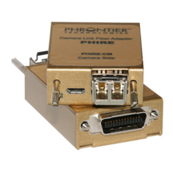
Each PHIRE module requires external DC power input within the range of 5V~24V. 12V is
recommended for optimum operation margin. A 5-pin micro USB type B receptacle is mounted
on the front panel of each module. Figure 2 shows the pin assignment of the power connector
on the modules.
A re-settable fuse is used for circuit protection in cases of over-voltage and over-current. The
over-voltage rating is 26.7V at 25
Exceeding those ratings will trigger the fuse and interrupt the input power.
Warning
When over-rating conditions occur, the input power circuit is not cut off but stays in high
impedance state. The re-settable fuse will continuously generate heat under the false
condition. Users must immediately remove the DC input power and investigate the root
cause of the false conditions.
Figure 2 Electrical Connection of DC Input Connector (Front View)
5.2. Camera Link Port & PoCL compatibility
Each of the PHIRE modules has a MDR26 male plug for directly connecting to a 3M MDR26
female connector as specified in the Camera Link interface standard. The Camera Link interface
of the PHIRE system is fully compatible with the Base configuration specified in the Camera
Link standard, which consists of up to 24 bit of image data, FVAL, LVAL, DVAL, SP, CC1, CC2,
CC3, CC4 and a bi-directional serial port (Figure 1). The exact bit assignment is defined in
Appendix C of the Camera Link standard. PHx-68 supports max. 24 bit of image data with up to
68MHz of pixel clock rate. PHx-85 supports up to 24 bit of image data with up to 85MHz pixel
clock rate.
The PHIRE system is designed to be compatible with Power over Camera Link (PoCL), which is
specified in Camera Link standard appendix E. The pin 1 and 26 on the MDR26 plug are
assigned for delivering or receiving electrical power. Summary of PoCL features are listed
below.
Warning
Only 12V DC power supply should be used for PoCL applications. The 12V DC input on
CM module is directly passed to camera PoCL pins without circuit protection.
D-A-CH
FrAnCe – Telecom
Laser 2000 GmbH
Phrontier Technologies
Laser 2000 SAS
82234 Wessling
78860 St-N. l. Bretèche
Tel. +49 8153 405-0
Tel. +33 1 30 80 00 60
www.laser2000.de
www.laser2000.fr
o
C. The over-current rating is 2.2A at 20
Pin 1
FrAnCe – Photonic
PHIRE User Manual V4
Laser 2000 SAS
33600 Pessac
Tel. +33 5 57 10 92 80
www.laser2000.fr
o
C and 1.6 A at 60
Pin 5
Pin 1 : VIN+
Pin 2 : Not connected
Pin 3 : Not connected
Pin 4 : Not connected
Pin 5 : VIN−
IberIA
Laser 2000 SAS
28034 Madrid
Tel. +34 617 308 236
www.laser2000.es
o
C.
6
norDICs
Laser 2000 GmbH
112 51 Stockholm
Tel. +46 8 555 36 235
www.laser2000.se
