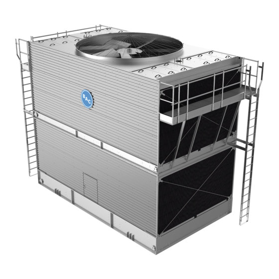
Baltimore Aircoil Company 1500 Series Manual de Instruções de Operação e Manutenção - Página 6
Procurar online ou descarregar pdf Manual de Instruções de Operação e Manutenção para Acessórios Baltimore Aircoil Company 1500 Series. Baltimore Aircoil Company 1500 Series 12 páginas. Crossflow cooling towers

Maintenance
Procedures
Quarterly, or more often if necessary, the entire cold-
water basin should be drained, cleaned, and flushed with
fresh water to remove the silt and sediment which
normally collects in the basin.
It is important to note that although stainless steel and
BALTIBOND
®
Corrosion Protection System — protected
basins provide added protection from corrosion, the
same maintenance applies to them as well.
If not removed periodically, this sediment can become
corrosive and cause deterioration of the protective finish
of metallic basins. When flushing the basin, the strainers
should be left in place to prevent the sediment from re-
entering the tower system. After the basin has been
flushed, the strainers should be removed, cleaned, and
replaced before refilling the basin with fresh water.
WARNING: Openings and/or submerged obstructions
may exist in the bottom of the cold-water basin. Use
caution when walking inside this equipment.
MAKE-UP VALVE:
A float operated mechanical water make-up assembly is
furnished as standard equipment on the cooling tower
(unless the unit has been ordered with the optional
electric water level control package or for remote sump
application). It is located inside the unit cold water basin
within easy reach from the access door at the connection
end of the unit on the Series 3000 and Series 1500
Cooling Towers.
The standard make-up assembly consists of a bronze
make-up valve connected to a float arm assembly and
actuated by a large diameter polystyrene filled plastic
float. The float is mounted on an all-thread rod which is
held in place by wing nuts. The operating water level in
the cold water basin can be adjusted by repositioning the
float and all-thread rod using the wing nuts provided.
The make-up assembly should be inspected monthly
and adjusted as necessary. The valve itself should be
inspected annually for leakage and the valve seat
replaced if necessary. The make-up water supply
pressure should be maintained between 15 and 50
psig for proper operation of the valve.
To set the initial basin water level, adjust the wing nuts so
that the make-up valve is completely closed when the
water level in the cold water basin is 1/2" below the
overflow connection. Under design thermal load and with
average city water pressure (15 to 50 psig) at the valve,
this setting should produce the operating water levels
stated in Table 2. Note that if the thermal load is less than
the design load at the time of unit start-up, the procedure
may produce operating levels greater than that shown. It
may be necessary to re-adjust the float in order to attain
6
(continued)
(continued)
Model No.
Series 3000 Models
33245 to 33501
Series 3000 Models
33522 to 331328
All Series 1500 Models
TABLE 2. Cold Water Basin Operating Water Level
the recommended operating level. The unit basin should
be closely monitored and water level adjusted as
necessary during the first 24 hours of operation.
As an option, an electric water level control package is
available in lieu of the above described mechanical
make-up assembly. The package consists of a probe-
type liquid level control assembly and a slow-closing
solenoid valve. Stainless steel electrodes, factory-set at
predetermined lengths, extend from an electrode holder
into the cold-water basin. These electrodes should be
periodically cleaned to prevent accumulations of
scale, corrosion, sludge or biological growth from
interfering with the electrical circuit. With the electric
water level control package, the water level is maintained
at the recommended operating level regardless of the
system thermal load. Therefore, it is not necessary, nor is
it recommended that the operating level be adjusted.
During the start-up of units equipped with the electric
water level control package, the control unit should be
bypassed in order to fill the unit 1/2" below the overflow
connection.
Operation at the recommended water level will ensure
that the unit basin contains sufficient water volume to
prevent air entrainment in the circulating pump during
system start-up and to provide sufficient excess basin
capacity to accept the total system pull-down volume.
("Pull-down volume" is defined as that quantity of water
suspended in the tower during pump operation plus that
contained in the water distribution system, external piping,
and any heat exchangers which could drain to the tower
cold water basin when the circulating pump is shut down.)
FAN MOTOR:
The standard fan motor used on Series 3000 and Series
1500 Cooling Towers is a T.E.A.O. motor (Totally
Enclosed, Air Over) with permanently lubricated ball
bearings and special moisture protection on the bearings,
shaft, and windings. The only servicing required during
operation is to clean the outside surface of the motor at
least quarterly to insure proper motor cooling. Additionally,
after prolonged shutdowns, the motor insulation be
checked with a "megger" insulation tester prior to
restarting the motor.
Height of Water in
the Cold Water Basin
(in.)
8
3
⁄
"
4
9
3
⁄
"
4
8
3
⁄
"
4
