esera automation 20002 Manual do utilizador - Página 3
Procurar online ou descarregar pdf Manual do utilizador para Acessórios esera automation 20002. esera automation 20002 4 páginas. Rain sensor 12v

Art. No. 20002
5
Connection
After unscrewing the sensor cover, the control cable is inserted into the cable gland M16.
The operating voltage is applied to the terminals VCC and GND. The potential-free changeover contact is connected
to the NC, COM and NO terminals.
6
Display
In the device there is a green LED for the operating indication and a red LED for the switching position indication
(relay contacts switched through).
7
Maintenance
The rain detector is largely maintenance-free. The sensor surface may have to be cleaned occasionally (e.g. once
a year, depending on the installation location) with a damp cloth. In the case of a continuous signal, even if it is not
raining, heavy soiling is to be assumed.
8
Assembly
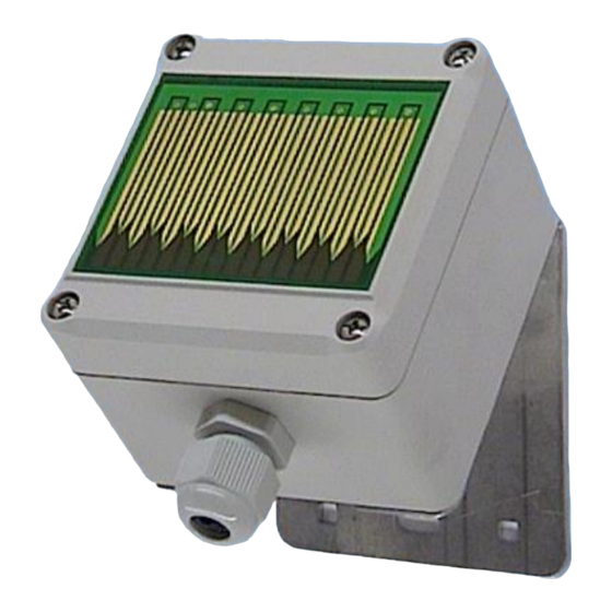
The rain detector can be mounted on a wall/pole bracket. If this is not used, a mounting angle of approx. 30° to
the horizontal must be observed. The tips of the sensor surface must point downwards. The rain detector should
be installed in a place that is freely accessible to rain. Dripping water can delay the switching back considerably
or lead to a permanent switching on/off.
9
Disposal instructions
Do not dispose of the device in domestic waste! Electronic devices are to be disposed of
according to the Directive on waste electrical and electronic equipment (WEEE) on local
authorities and collection points for waste electronic equipment!
10
Safety instructions
When handling products that come into contact with electrical voltage, the applicable VDE regulations
must be observed, in particular VDE 0100, VDE 0550/0551, VDE 0700,
VDE 0711 and VDE 0860.
The device is only designed for low voltage and must not be operated with mains voltage!
The relay contact is only designed for small signals and must not come into contact with mains voltage!
The degree of protection is only given with an intact, complete housing, the cover screws and the PG screw connection must
be tightened firmly, the cover seal must be continuously present in the sensor cover!
The suitability for a certain application must be checked by the user!
All final or wiring work must be carried out with the power turned off.
Before opening the device, always unplug or make sure that the unit is disconnected from the mains.
Components, modules or devices may only be put into service if they are mounted in a contact proof housing.
During installation they must not have power applied.
Tools may only be used on devices, components or assemblies when it is certain that the devices are disconnected
from the power supply and electrical charges stored in the components inside the device have been discharged.
Live cables or wires to which the device or an assembly is connected, must always be tested for insulation faults or
breaks.
If an error is detected in the supply line, the device must be immediately taken out of operation until the faulty cable
has been replaced.
When using components or modules it is absolutely necessary to comply with the requirements set out in the
accompanying description specifications for electrical quantities.
If the available description is not clear to the non-commercial end-user what the applicable electrical characteristics
for a part or assembly are, how to connect an external circuit, which external components or additional devices can
be connected or which values these external components may have, a qualified electrician must be consulted.
It must be examined generally before the commissioning of a device, whether this device or module is basically
suitable for the application in which it is to be used.
In case of doubt, consultation with experts or the manufacturer of the components used is absolutely necessary.
For operational and connection errors outside of our control, we assume no liability of any kind for any resulting
damage.
Kits should be returned without their housing when not functional with an exact error description and the
accompanying instructions. Without an error description it is not possible to repair. For time-consuming assembly or
disassembly of cases charges will be invoiced.
All rights reserved. Reproduction as well as electronic duplication of this user guide, complete or in part, requires the written consent of
ESERA GmbH. Errors and technical modification subject to change. ESERA GmbH, ESERA-Automation 2020
www.esera.de
20002 V2.0 R1.0 Manual
Page 3 of 4
