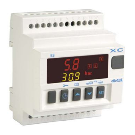
dIXEL XC450D Instruções de utilização
Procurar online ou descarregar pdf Instruções de utilização para Controlador dIXEL XC450D. dIXEL XC450D 3 páginas. Safety step controller

dIXEL
SAFETY STEP CONTROLLER
XC450D
GENERAL WARNING
PLEASE READ BEFORE USING THIS MANUAL
This manual is part of the product and should be kept near the instrument for easy and
quick reference.
The instrument shall not be used for purposes different from those described
hereunder. It cannot be used as a safety device.
Check the application limits before proceeding.
SAFETY PRECAUTIONS
Check the supply voltage is correct before connecting the instrument.
Do not expose to water or moisture: use the controller only within the operating limits
avoiding sudden temperature changes with high atmospheric humidity to prevent
formation of condensation.
Warning: disconnect all electrical connections before any kind of maintenance.
The instrument must not be opened.
In case of failure or faulty operation send the instrument back to the distributor or to
"DIXELL S.r.l." (see address) with a detailed description of the fault.
Consider the maximum current which can be applied to each relay (see Technical
Data).
Ensure that the wires for probes, loads and the power supply are separated and far
enough from each other, without crossing or intertwining.
Fit the probe where it is not accessible by the end user.
In case of applications in industrial environments, the use of mains filters (our mod.
FT1) in parallel with inductive loads could be useful.
GENERAL DESCRIPTION
TECHNICAL FEATURES
Housing: Self extinguishing ABS.
Case: 4 DIN modules 70x85 mm; depth 61mm
Mounting: DIN RAIL
Protection: IP20
Display: upper display 3 digits with d.p. lower display 4 digits with d.p.
Connections: Screw terminal block 2,5 mm
Power supply: 120Vac
10%,50-60Hz or 230Vac
Power absorption: 5VA max; Probe input: for 4÷20mA signals.
Digital inputs: 6 free voltage.
Data storing: on the non-volatile memory (EEPROM).
Relay outputs: 6 relays SPDT 8(3) A, 250Vac.
Operating temperature: 0÷60 °C.; Storage temperature: -30÷85 °C.
Relative humidity: 20
85% (no condensing).
Measuring range: -40÷110 °C (- 40÷230 °F) or 4÷20mA;
Resolution: 0.1 °C or 1°F (selectable);
Accuracy (ambient temp. 25°C): ±0,7 °C ±1 digit.
1592001620 XC450D GB R1.0 10.07.2009
Operating instructions
XC450D is a safety step controller with 3 setps
that excludes the main regulator when it has a
fault. It detects the compressor status by a free
voltage digital input that is activated after a
settable delay. It manages a relay that
excludes the main regulator of the compressor
rack and starts the safety regulation. It is
provided with pressure transducer input, 4÷20
mA, while the regulation is performed by three
relays.
It has a HP digital input, and a liquid level
digital
input
both of them free voltage,
Furthermore the safeties of each compressor
can be connected to a dedicated free voltage
digital inputs.
By means of the HOT KEY the controller can
be easy programmed at power on.
The controller can be connected to the XJ500,
controlling and monitoring system, thanks to
the serial TTL output, using the standard
ModBus RTU protocol.
2
heat-resistant wiring.
10%,50-60Hz or 24Vac
WIRING CONNECTIONS
Probes
4-20mA: use terminals 9(+) 11(in)
MOUNTING & INSTALLATION
MOUNTING
The XC450D shall be mounted on an omega DIN rail. The temperature range allowed for
correct operation is 0÷60 °C. Avoid places subject to strong vibrations, corrosive gases,
excessive dirt or humidity. The same recommendations apply to probes. Let air circulate by
the cooling holes.
ELECTRICAL CONNECTIONS
The controller is provided with screw terminal blocks for wires having section not bigger
2
than 2.5 mm
.
Check power supply data before connection wires.
Keep the probe and the digital input wires separate from the power cable.
Do not exceed the maximum rating current for each relay, check technical data and if the
load is bigger, use filtered contactors.
Before connecting cables make sure the power supply complies with the instrument's
requirements. Separate the input connection cables from the power supply cables, from
the outputs and the power connections. Do not exceed the maximum current allowed
on each relay, in case of heavier loads use a suitable external relay.
PRESSURE TRANSDUCERS
Pressure probe (4 - 20 mA): respect the polarity. If using terminal ends be sure there are
no bear parts which could cause short circuiting or introduce noise disturbance at high
frequencies. To minimise the induced disturbances use shielded cables with the shield
connected to earth.
RS485 SERIAL LINE
All models can be integrated into the WEB monitoring and supervising systems using the
TTL serial port. They use the standard ModBus RTU protocol, so they can be fitted in a
system integrator using this protocol. Check the product library presence if the version is
previous to this model.
XJ485CX INTERFACE
USER INTERFACE
XC450D
1592001620
Interface: XJ485CX
Colour: orange
Code: XJ485CX-00000 + CAB/RS 0.2MT
(with 20cm cable).
Upper display: OFF when the regulation
is disabled. Pressure probe value during
regulation mode.
Lower display: delay time when the digital
input is ON.
1-2-3 Icons: loads output if set as
compressor. Flashing with call delay.
°C /°F: temperature value
Bar/Kpa/PSI: pressure value
Spanner: maintenance menu for
loads time
Open book: alarm storing
Alarm is happening
1/3
