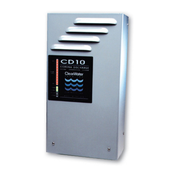
ClearWater CD12 Procedimento de manutenção anual - Página 2
Procurar online ou descarregar pdf Procedimento de manutenção anual para Filtro de ar ClearWater CD12. ClearWater CD12 3 páginas.

Reaction Chamber Removal and
Disassembly:
Note: Read through all the steps before disassembling the reaction
chamber.
Step 1: Make sure all power to the ozone generator has been
disconnected according to the "System Shutdown Procedures"
outlined above.
Step 2: Disconnect the high voltage lead from the reaction chamber(s).
Step 3: Disconnect the tubing connections on both ends of the reaction
chamber(s).
Step 4: Remove the 4 nuts securing each chamber and remove the
reaction chamber from ozone generator.
Step 5: Make note or mark the position of the end caps and their elbow
fittings on the reaction chambers, during re-assembly the end
caps will need to return to original positions. The orientation of the end caps and the chamber itself is different between the two CD12 chambers.
Step 6: Remove retaining screws and washers from the two end caps (3 each).
Step 7: Using a gentle back-and-forth twisting motion, remove the non-high voltage end cap (the one without the high voltage attachment screw) from the heat
sink/cathode assembly. A flat-head screwdriver may be used to gently pry the end cap off, as long as equal pressure is applied to each side of the end cap.
Step 8: Remove the high voltage end cap and dielectric from the heat sink/cathode assembly.
Step 9: The high voltage end cap can be removed by holding the glass and turning the end cap counter-clockwise approximately 6 turns. Pull the end cap off the glass.
Push the contact brush out of the dielectric glass. A screwdriver can be used to push the brush, and pliers to pull it out once the opposing end is exposed.
Step 10: Inspect the dielectric, end caps and cathode for breakage, corrosion or debris; then follow the assembly and re-installation steps below.
Reaction Chamber Assembly and Re-installation:
Step 1: Remove o-rings from end caps, clean the dielectric glass, end caps and interior of the stainless steel cathode cylinder. Use denatured alcohol, shop towels to
clean and be sure to remove all old o-ring debris. A 1" ball hone can be used to clean the major debris out of the cathode if there is heavy buildup.
Step 2: Prepare the end caps for re-assembly by replacing the o-rings. Thread the hex brush adapter nut, with contact brush attached, onto the end of the high voltage
end cap (cap with the high voltage attachment screw) center screw. Re-tape the threads of the elbow fittings if needed.
Step 3: Using a gentle twisting motion, press the non-high voltage end cap onto the heat sink/cathode assembly until flush with the heat sink cooling fins. Turn the end
cap to the correct orientation.
Step 4: Slide the three end cap retaining screws with washers through the holes in the non-high voltage end cap, aligning them with the heat sink screw bosses. Thread
screws into screw bosses until heads are snug against the end cap.
Step 5: Next we focus on assembling the rest of the subcomponents, before installing them into the reaction chamber. Slowly insert the brush (installed onto the high
voltage end cap) into the dielectric glass. Note: Go slowly in order to prevent or minimize bending the center wire of the brush during this procedure. It is
normal for the bristles to bend flat against the dielectric glass. Fully seat the dielectric glass into the high voltage end cap. Clean the glass with denatured
alcohol once more, and do not retouch the glass without re-cleaning.
Step 6: Hold the reaction chamber upright on a flat surface, empty high voltage side up. Grasp the high voltage end cap and lower the glass into the reaction chamber.
Press directly downwards on the high voltage end cap to fully seat the dielectric assembly; the end caps should be flush with the heat sink cooling fins. Turn
the end cap to the correct orientation.
Step 8: Slide the three end cap retaining screws with washers through the holes in the end cap, aligning them with the heat sink screw bosses. Thread screws into screw
bosses until heads are snug against the end cap.
Step 9: Re-install the complete reaction chamber assembly into the ozone generator by securing the reaction chamber to its mounts, securing delivery line and
connecting the high voltage insulated wire.
ClearWater Tech, LLC.
1.800.262.0203 • 805.549-9724
850-E Capitolio Way, San Luis Obispo, CA 93401 • email: [email protected] • www.cwtozone.com
Annual Maintenance Procedure
FOR USE WITH CD10, CD10/AD, CD12 & CD12/AD
Page 2
LIT228 Rev.100912
